Friday, 12 October 2018

Revit 2019 Tutorial Part 1 – Adding Vertical Bracing Systems

Many people still ask me what the best methods are for adding bracing to steel models.

Some are still using beams to try and model bracing, others get into a bit of a mess with vertical bracing, and many struggling with the representation on drawings.

Therefore, I thought it was about time I created a Revit training tutorial on this, covering horizontal bracing, vertical bracing, and some typical connections for adding those all-important details.

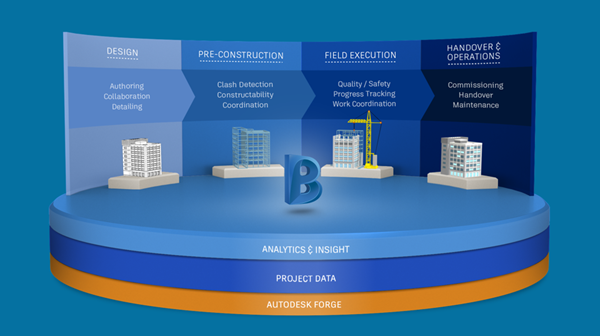
First, we need to look at some of the basics. Below you can see examples of Vertical, Horizontal and Roof Bracing.
When creating vertical bracing, it’s ideal to create a framing elevation which provides an elevation of a few hundred millimetres deep and sets a working plane for the bracing.
Use the dedicated brace command to efficiently add bracing.

This enables you to roughly sketch the required bracing and then use the Properties Palette to fine tune the exact location of the bracing.

In the image below, you can see some vertical X-bracing with the start and end attachments attached to the correct levels, with the option of adding offsets from each of these levels.


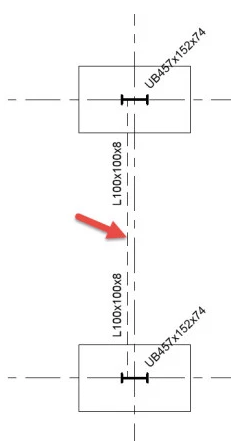
I have used the Equal Angle to create the bracing, with both angles in the same plane, hence the clash.

This can easily be resolved by using the y offset value on each member. The analytical line remains centred, but the physical elements will be located correctly.


The bracing is automatically represented in a plan view and can be marked. The standard in the UK is to show a parallel line on the outside for bracing above and a parallel line on the inside for bracing below.

You can control the type of representation and spacing in the Structural Settings dialog box.


Finally, if you want to tidy up the bracing and make the drawings look a little better you can either use 2D detail components to represent a connection or use the connection tools to add 3D connections.

This is just one area you will learn more about by attending one of our Excitech’s Revit Training courses.

This article was originally posted on the Revit Structures Blog page.

Wednesday, 8 August 2018

AEC Workflow for Visualisation and VR


by Geoff Alder

I have been delivering training on Autodesk software for thirty years and during that time I have seen many developments and changes to the way industries adopt the software.

AutoCAD was and still is excellent at modifying the geometry. Therefore, AutoCAD became a tool very proficient at editing in the developing progression of a project. I use the word “tool” here because the technical drawing was an evolving document and a tool to edit changes was needed. “I need to change what I have to what I want”. As a carpenter, I would use a plane to smooth sawn timber to have a smooth surface. It is a specific tool to do a job. I selected a plane to smooth the rough sawn timber.

The AEC Collection has many “tools”. AutoCAD has evolved unrecognisable in the last thirty years. We also have 3ds Max, we have Revit and Revit Live. We also have 3ds Max Interactive. These are excellent Autodesk software solutions and perform very specific and capable tasks. Many clients I visit and indeed train are looking for greater understanding of the full AEC Collection. They say that they have AutoCAD operatives, Revit operatives and 3ds Max visualisers however, the focus should be on being a professional designer not a software operative. We need the Autodesk software to edit the design so we need to select the correct tool to edit and achieve our design.

In interior design the toolset can be quite comprehensive. Much of the design will utilise a great deal of the AEC Collection and other software with regards to image manipulation.

I believe- getting back to my early training- that using the best tool for the job leads us to focus on workflows. The AEC Collection is an excellent set of Autodesk software tools. You don’t need a comprehensive understanding of each software in the collection. You need to know the correct tool to do the job.

My workflow training for Interior design to VR really must look at the best tool for the job. AutoCADRevit, Revit Live, 3ds Max and 3ds Max interactive are the primary tools in the Collection. Let’s look at the design and choose the correct tool to evolve the design. A rather famous quote says “When you only have a hammer everything is treated as a nail”.

Saturday, 21 July 2018

On Track with Dynamo and Revit at Autodesk University London

by Lawrence Hooker, Excitech
I recently attended Autodesk’s main UK learning event, Autodesk University London at Tobacco Dock in London’s East End. The two days were filled with industry presentations, hands-on-labs and plenty of opportunities to network and connect with like-minded individuals.

The general theme for most of the event was the increasing use of automation and convergence of the design, manufacture and construction industries. One of the highlights was listening to Jaimie Johnston of Bryden Wood discussing how they have used software technologies such as 
AutodeskDynamo to automate the design and installation of highly complex panels for the Crossrail project.

I was lucky enough to be able to present a class on the automation of trackside structures using 
Autodesk RevitCivil 3D and Dynamo with a little Infraworks and Recap for as-built structures.

During the presentation, we explored the automated design of rail platform structures and looked at parameters and data to assist with the setting out of the precast components for the construction phase. The workflow below shows how you can capture an existing platform and then use the Autodesk 
AEC Collection to process and index the scan data, extract features using Autodesk Infraworks and then utilise Autodesk Dynamo, Civil 3D and Revit to produce detailed design and construction drawings.

Most of the structures are related to the centreline of the rail track and, as such, can be offset and automated with Dynamo. For example, the platform has a precise offset and level from the rail that follows the cant and vertical profile. This very fact makes it extremely efficient to place the elements with Dynamo, especially when the track is on a curved alignment.

Explore Autodesk's AEC Collection here

A recording of this AU London presentation is available here.

Monday, 25 June 2018

Understanding the Autodesk “Switch”

Since the introduction of term-based subscription licensing from Autodesk, the options for customers and the way they purchase licences has changed considerably. New perpetual licences were discontinued for new sales in 2016, with those on maintenance plans offered the option to switch to subscription in 2017. There are several implications to switching, but first, it is important to understand what it means.

Let’s start by separating the various “switch” scenarios.

  1. Subscription to a Collection: an existing individual product subscription is converted to an Industry Collection
  2. Maintenance to Subscription: a maintenance plan is converted to a subscription for a comparable product
  3. Maintenance to a Collection: a maintenance plan for an individual Autodesk software product is converted to a subscription to an Industry Collection
The first scenario involves moving an existing subscription to an Industry Collection and is only available to customers who are already on a subscription for an eligible product or design suite.  This does not change the current licensing model, it solely changes the product currently subscribed to.


Scenarios 2 and 3 on the other hand involve relinquishing a perpetual licence on maintenance plan for a subscription, entirely moving to the new licensing model. At the time of switching, you can choose to move to the same Autodesk software product (option 2), or to an Industry Collection, such as the AEC Collection (option 3). These options are only available 90 days before your maintenance plan expires, with new subscription contracts active the day after expiration.


The key difference when moving to subscription from maintenance, is that your price, for same product switches is approximately the same as your maintenance plan, significantly lower than a newly purchased subscription. Moving to a Collection affords an approximate 60% discount when compared to a new Collection subscription. 


To explore your licensing options watch our video explanation.


As a general rule of thumb, for customers who use two or more Autodesk software products per user, moving to a Collection is often the best route. The Architecture, Engineering & Construction Collection (AEC Collection) has seen considerable improvements since its introduction. Additional products such as Advance Steel, Fabrication CADmep, Robot Structural Analysis to name a few, are offering customers additional functionality, improved workflows and in some cases, lowering the overall licence requirement.

There are a myriad of options and considerations for your licence management – and we recommend you talk to us. We can evaluate your requirements and advise on the best options for you moving forward.

Wednesday, 30 May 2018

What You Need To Know About SketchUp Layout


SketchUp is one of the most popular 3D modelling software solutions in the world.

Here are a few key facts:
  • 33,500,000 Annual Activations
  • Over 1,000,000,000 completed Projects using SketchUp
  • 109,000 followers on Twitter
  • 759,000 followers on Google +
  • 370,000 likes on Facebook

An intuitive and quick to learn 3D conceptual design modelling platform, SketchUp enables more participation and collaboration across workflows.

However what is less known is the Layout tool in SketchUp and I’ve been asked many times recently “What is Layout, what does it do”?

LayOut is a tool for creating documentation from your SketchUp model and is part of the SketchUp Pro Suite.

Layout combines SketchUp models with text and 2D vector illustration to help you produce beautiful presentations, permit submittals, construction documents, and other dimensioned drawings. It allows you to produce professional drawing sets, provides powerful dimensioning, drawing and page layout tools to create working drawings and presentations from SketchUp models.

How it works

You start in SketchUp, draw your project and create scenes to show the different views. You can send the file to LayOut, add dimensions, labels, other text, photos and then export a PDF file to send to a client or use it to do a presentation on screen.
The dynamic link between the SketchUp model and the LayOut document means that any edits you make in your SketchUp model, will be reflected in the LayOut document. Drawings can also be exported as DWG/DXF files for use in any CAD program and you can combine dimensions, text, and graphics, add logos and title blocks to LayOut templates for brand consistency.

LayOut also has the ability to assign different drawing scales to SketchUp model views and dimension them without leaving LayOut and without using a separate CAD tool.

Drawings are dynamically linked to 3D models and SketchUp models are dynamically linked to your LayOut file so any changes you make in SketchUp are automatically reflected in your documents.

Lastly, you can link to files in the cloud via Dropbox, Google Drive or Trimble Connect.
  
A single LayOut document can be used for both printing and on-screen presentations as well as to create high-resolution large format prints which you can export as PDF files for onward distribution, or to present directly from the application... in 3D.

Explore LayOutby watching the videos below:


To learn more about SketchUp, please contact Excitech – https://www.excitech.co.uk/Products/SketchUp-Pro

Friday, 20 April 2018

Increase Virtual Memory to Boost Revit Performance

A critical factor in the speed and performance of your computer is the amount of Random Access Memory (RAM) that is installed.

Adding more RAM should improve the performance of Revit and your computer; however, even a computer with a fast CPU can run slowly without the proper amount of RAM.


If you have been working away and have received the following message below stating that your system is running low on virtual memory, then you are not alone, and there are several different solutions you can use to resolve this issue. Of course, upgrading your current RAM would be the obvious solution, but there is another temporary measure you can take that can prevent this message from appearing and even enhance the performance of your system.


This is a great procedure to follow when attempting to temporarily boost the performance of systems where Autodesk applications such as Revit is having difficulty importing or exporting geometry or handling larger assemblies. What this means is that it gives the operating system the extra room it needs to manoeuvre should it run out of physical memory. The Virtual Memory is not used until the Physical RAM in the system has been exhausted and the system requires somewhere to hold additional information. The following trick is carried out on Windows 7. This process can also be replicated for those using Windows 8/8.1 and Windows 10.

First, determine how much memory (RAM) you have installed on your system. To find this out, right-click Computer, then click Properties. The amount of RAM installed and available is displayed in red as highlighted below:


Click the Start button, right-click Computer, and then click Properties..


In the left pane, click Advanced system settings.


On the Advanced tab, under Performance, click Settings


Click the Advanced tab, and then, under Virtual memory, click Change


Finally, ensure that you clear the Automatically manage paging file size for all drives check box. Then under Drive [Volume Label], click the drive that contains the paging file you want to change and select Custom size, type a new size in megabytes in the Initial size (MB) or Maximum size (MB) box, and select Set, and then click OK. As shown below:


IMPORTANT NOTE:

As a final note, just increasing the virtual memory does have some drawbacks. The disk has less space for other uses, since a larger portion of it is reserved for this swapping size, hence using so much memory means it will run much slower than only using the amount of physical RAM, but if you needed to increase (e.g. was crashing with out-of-memory warning message) then it may not crash anymore. The power consumption is another factor that may increase as a lot more disk access is happening, which tends to be less efficient than simply accessing the physical RAM, hence this may cause the disk to fail sooner due to more usage. In the long run, however it is important that you install the maximum allowed RAM by your computer’s motherboard, as a permanent fix to the underlining issue.

We hope you found this tip useful. Check back on our blog for more tips & tricks to keep you productive.

Friday, 9 March 2018

The Essentials Of Energy Management For Facilities Managers

It’s vital to monitor all aspects associated with energy management whether you’re operating a large or small organisation.

For an organisation, their first challenge is to assign responsibility for all aspects of energy management. This person or team will keep the estates energy usage in line with the organisations goals set by the directors.
 
The next piece of the puzzle is selecting the most appropriate Facilities Management sensors and software to provide full visibility of an estate and its energy usage. Having the right sensors and software in place helps the facilities team to easily gather data and evaluate usage, enabling them to optimise and utilise spending decisions to reduce unnecessary consumption and costs.


With an appropriate facilities management software in place, the next immediate challenge is to select an energy supplier and the correct tariff. Matching the tariff to the business usage can be difficult, and estimating future needs may require expert help. Your CAFM software will automatically record the estates energy usage, and will store historical data to identify the facilities trends. This enables the facilities management team to actively manage energy in real-time, identifying potential issues, implement corrective actions, and manage usage.
 
Once the CAFM solution is in place and the challenges are understood, implementing corrective action is the key to reducing usage, saving the environment and saving the organisation money. This can be done by establishing a behavioural awareness program to increase awareness when using energy on the job. Embedding an energy conscious culture is the quickest way to reduce usage. This can be introduced at site inductions, education schemes and training session provided by the organisation.
 
CAFM software like ARCHIBUS has demonstrated a reduction in energy usage of up to 5%, which represents a significant saving for any organisation.


Monday, 19 February 2018

Digitise The Construction Site

The BIM 360 Suite of cloud-based products offers a wide range of solutions to make design, construction and handover processes much more efficient.

BIM 360 Field is built for construction management processes such as managing quality, health and safety and commissioning which allows for easy information capture and review out on site. By utilising the cloud, project performance can be easily understood using intelligent reporting and dashboarding.  


We capture and distribute a large amount of data in construction on a daily basis including emails, drawings, specs, RAMS or health and safety information. This data lives in various locations in various formats such as PDFs, Word and Excel. BIM360 Field enables capture of this data in a digital format or database which can then be updated, reused, reported on and shared with the project team instantly.

For example, a site manager does their site walk, taking photos and notes of any issues they come across. They then go back to the site office and spend time transferring the photos from their phone onto their PC to begin the resolution process via email. The more time we can save removing tedious tasks, the more time can be spent out on site making sure that works are being carried out correctly and in a safe manner.

This type of thinking is nothing new, we use social media on a day-to-day basis in our personal lives to manage our communication (group chats), photos and videos. We upload a photo, tag people and they have instant access, we can then communicate with our friends and family around that particular photo. Manging data on site should work in exactly the same way. 

Moving to the cloud, capturing and re using data in new ways is the future of our industry and our world. Autodesk are at the forefront of Artificial Intelligence in construction and so the next generation of BIM 360 is now available for public beta-testing which combines what are currently separate modules (BIM 360 Glue, BIM 360 Field, Docs and Plan) into a unified platform. This opens up doors to a totally new way of working and integration with other systems, using their new platform built on Forge technology.


To learn more about BIM 360 Next Generation, please sign up to our BIM 360 newsletter.

Wednesday, 13 December 2017

Creating Custom Content using Pinnacle Series


Pinnacle Series is an interactive e-learning and productivity platform developed by Eagle Point Software that connects people to the answers they need, when they need them. From Autodesk-specific training to HR processes and procedures, this platform can support a plethora of content, tailored to your organisation’s needs. 


Our most recent Pinnacle Series webinar presented the software’s content creation capabilities, and featured Phil Sawyer, BIM and IT Director at architectural practice ADP, a proficient Pinnacle Series user who is using Pinnacle to drive their in-house skills training.
The webinar started with a presentation of the problems that this e-learning and productivity platform can help managers solve. Jeff Rouse, Content Development Manager at Eagle Point Software focused on three challenges that management staff are confronted with:

  • Staff trying to complete work “their way”, often using incorrect methods
  • Teaching staff to use the tools they have 
  • Allowing staff to help themselves when encountering a problem, using vetted troubleshooting tools

The webinar started with a presentation of the problems that this e-learning and productivity platform can help managers solve. Jeff Rouse, Content Development Manager at Eagle Point Software focused on three challenges that management staff are confronted with:

  • Staff trying to complete work “their way”, often using incorrect methods
  • Teaching staff to use the tools they have
  • Allowing staff to help themselves when encountering a problem, using vetted troubleshooting tools

Another aspect of Pinnacle Series that Jeff presented was the fact that content can be customised to suit the requirements and training needs of different departments. One Learning Path can focus on the Onboarding of New Employees and can include different courses from different departments (Technical, Sales etc.), whilst another could focus on the Fire Exit Procedure. This feature gives Content Managers a lot of flexibility in the way they build workflows for different types of employees.

Jeff’s presentation was followed by Phil Sawyer’s who spoke about how his company – ADP - uses Learning Paths to train staff. According to Phil, “Pinnacle Series is very good to train new people to use new software, allowing them to be productive very early on.” He also emphasised the ability to run quizzes which enable line managers to understand if employees are learning and retaining new information.


To learn more about this award-winning e-learning and productivity platform, please contact us.

To watch the webinar recording, please click on the image below.

Wednesday, 15 November 2017

Enabling Revit to produce BIM

There is often confusion around BIM and Revit, we often hear people saying, ‘This project is being done in BIM' but when we look a little further they often mean ‘This project is being done in Revit.’ The distinction between BIM and Revit is not clear to some.

Revit creates 3D models capable of holding real world information about the model. This information is a requirement for BIM. To produce BIM compliant models from Revit, you must first know what information you are required to deliver with your model.

Once you have this established, you need a strategy in place to populate the information and deliver it in the required format. In Revit, this will involve having Shared Parameters for the relevant information fields. Depending on the format required, the shared parameters may come from the Project Information Manager, or they may be industry standards such as COBie and NBS.

These parameters will need to be added to the Revit project when required or incorporated into your company Revit Project template.

There are also many plug-ins that can help automate this task. Ideate BIM Link, Autodesk COBie Extension, NBS Create, CTC BIM Suite to name but a few. A Dynamo graph could be configured to automate filling in some information directly, or to interface with Excel too.

Once we have an information rich model, we need to think about delivery. What format is required by the client: the native Revit model, an IFC file, an upload to a specific Common Data Environment system that will extract the information? Whichever it is, we need to plan for this and allow time to create the deliverable model.

The live, WIP Revit project will need purging, views and sheets stripped out, design options removed. The appropriate name and revision will need to be applied to the model and then issued out to the appropriate recipients in the agreed format.

In summary, using Revit to create Building Information Models is not difficult but does take planning. We need to be aware of what we’re required to deliver and have a strategy for populating the information. We have to allow for the time required to publish and share the models, this includes checking that the information is correct and approving the deliverables. 

Thursday, 12 October 2017

Facilities Managers (FM) must be Engaged in the Pre-Design Process. How can CAFM Software Support?

Facilities managers (FM) must be engaged in the pre-design process

Far too often the facilities management team are not engaged with when an owner or occupier is specifying the EIR (Employer's Information Requirements) and AIR (Asset Information Requirements) for a new build. This is despite them having the greatest need for accurate buildings information at the end of the design process. This lack of involvement is leading to data being passed on in an unusable format, without the required level of detail and information, leading to costly and time consuming re-surveying of a building.

Is COBie the answer?

COBie is an international standard for building data exchange. Its most common use is in product data handover from construction to operations. Agreement to use the COBie format should theoretically stop these data issues arising.

If an FM is not engaged within the pre-design stage or does not fully understand the process, then they will not get the required columns populated in a format that they can easily import to their CAFM software.

How can software support?

Archibus facilities management software can import data directly from the design and construction model, which allows owners and occupiers to gather information above and beyond what has initially been specified. This however is not best practice, as key data may still not be captured in the model during the process, unless it is specified at the outset.

Facilities managers know what information they will need to manage a building throughout its lifetime. As more buildings are delivered through the BIM process, it becomes more apparent of the immense potential of the outputs available. To save a great deal of time and money, it is advised to involve these experts as early as possible in the specification process.

For more information about facilities management software, please visit our website http://www.excitech.co.uk/Solutions/CAFM-Software

What’s New in AutoCAD Electrical 2025

This blog will examine what’s new in AutoCAD Electrical 2025. Automatic Reports Enhancement In AutoCAD Electrical 2025, you can now cre...