Showing posts with label Civil 3D. Show all posts

Monday, 23 October 2023

What are the five steps towards reaching ISO 19650 Accreditation?

ISO 19650 is an International suite of standards for managing information over the whole life cycle of a built asset using building information modelling (BIM).

Since the end of 2022, the construction industry experienced a shift in organisations investigating this standard and the accreditation process in more detail since the UK Accreditation Service, UKAS, announced the accreditation of three certification providers under this banner.

If you would like to know more about the ISO 19650 standard or you are ready to start moving towards certification, Daryn Fitz Principal Consultant and Special Projects Lead at Symetri, explains the 5 steps you need to follow in this short video: 


For more information, read of blog: 

https://www.symetri.co.uk/insights/blog/how-do-we-become-bim-iso-19650-2-accredited/

Or to book an appointment to discuss your company's journey, complete the form on this page https://www.symetri.co.uk/campaigns/bim-surgery/

Monday, 19 June 2023

WEBINAR RECORDING | Exploring the new features and workflows in Autodesk Civil 3D 2023

Autodesk Civil 3D is a software solution that supports a wide range of survey and civil engineering tasks. It helps anyone creating supporting documents for civil design, transportation work, or land planning and development to create intelligent relationships between objects so that design changes update dynamically.

With each new release of Autodesk Civil 3D, new and improved features are included. In this version, the new features cover a variety of areas, including spatial analysis and infrastructure and utilities design.

In this webinar recording, we discuss the latest updates and features in Civil 3D 2024, including:

-          Project Explorer

-          Corridor Transitions

-          Subassembly Deployment & Management

-          Pressure Network Layout & Editing

-          Connector for ArcGIS

Watch the recording here:


If you have any questions or need any support. Please feel free to get in touch with Symetri on info@symetri.co.uk or 0345 370 1444.

Thursday, 20 April 2023

AUTODESK CONSTRUCTION CLOUD – COLLABORATION BETWEEN DISCIPLINES

In the past few years, the word “collaboration” is applied to all discussions on improving organisations within the AEC industry, and indeed the industry as a whole. And rightly so. A number of historical problems in the industry can be associated with failures in collaborative efforts, which isn’t a surprise. Projects involve numerous parties, constantly exchanging masses of knowledge over time (often years), in various formats, via varying workflows and practices and in alignment with a host of requirements. How could everything possibly be done correct? Well, honestly, it can’t. However, we can certainly get the rate of error much nearer to zero and lessen the impact of misfortune when it does occur. How, may you ask? Through the use of skill, and tools.

One tool being Autodesk Construction Cloud (ACC). ACC is a powerful collaboration platform, allowing AEC professionals to work cooperatively seamlessly across the different disciplines. The platform provides a range of both tools, and features enabling team members to share data, communicate effectively, and collaborate on a variety of project tasks, from Design to Operations. In this blog, we will discuss how ACC can be used across disciplines, to help improve communication and collaboration (and there is that word again!).

Autodesk Docs

As the Common Data Environment for ACC, Autodesk Docs holds a number of very valuable tools, which help teams coordinate in an assortment of different ways.

You can utilise ‘Transmittals’ to notify other teams of updates, and ‘Permissions’ enabling teams to view only the data that is correct and relevant to them. ‘Markup’ and ‘Commenting’ allows stakeholders have their say in documents, including drawings and models, where previously they might have needed specialist software licencing, as well as knowledge to have their say. ‘Issues’ is the centrally accessible tool used for tracking and resolution, which can be personalised for different kinds of Issues (like Fire), and even linked to Revit allowing pins flagging clashes or other items to be shared directly between different teams, using the free add-in.

And of course, everything is versioned in Autodesk Docs with the capability to view older revisions of files and documents, and even roll back to one of these revisions. This also allows the ability to compare the versions of drawings and models, to gain a full understanding on the impact of any changes that have been made.

Design Collaboration

Design Collaboration’s purpose is to overcome the time old problem of using incorrect, or dated information given from other teams. The focal point of the module is the swim lanes, which effectively visualise when “Packages” are distributed between each design team. Depending on the appearance of these “Packages” on the swim lanes, it both indicates the high-level contents and whether your workforce has retrieved the data to your own folders, in a process called “Consuming”.

These features allow teams to control the flow of their knowledge, including both ingoing and outgoing, as well as monitoring changes in an easy to manage, visual based environment.

Model Coordination

Focusing more on the 3D aspect of cooperating with other teams, the Coordination module enables teams to run both cross-discipline and internal clash checks, updating automatically when latest models are uploaded. This can be achieved across a variety of formats (detailed below), meaning coordination is accessible to all parties involved, no matter what software they are using. Issues are then able to be created of items of interest found and assigned to either internal or external teams.


When designing in Revit, these clash issues can be presented and reviewed directly within the model, using the forementioned issues add-in.

For those companies with embedded clash detection process in Navisworks, the add-in allows models and views to be opened straight from Model Coordination. Issues can be made directly in Navisworks and synchronised automatically with ACC.

Collaborate Pro

Utilising the cloud sharing capabilities of Revit, Civil 3D and Plant 3D, Collaborate Pro allows work shared models to be hosted on ACC. Collaborate Pro users additionally have all the advantages included in Design Collaboration and Model Coordination.

Autodesk Build

Autodesk Build provides tools that are regularly used during the Construction stage, from Project Management to Quality to Project Closeout. It can be used to oversee project workflows, track project milestones, as well as communicate with internal or external team members. Teams that are on-site can use Autodesk Build to manage inspections, issues, and tasks, guaranteeing that construction progresses both smoothly and on schedule. RFI’s can be issued to communicate the need for extra information from either the client, or other stakeholders.

The Conclusion

Autodesk Construction Cloud is armed with a myriad of capabilities, helping support AEC professionals within the industry across organisations to achieve a collective goal. If collaboration is important to you and your projects, and you’d like to find out how we have assisted past clients in the ACC platform or BIM, and how we can help you too, please get in contact with us to book in an appointment.


Monday, 6 March 2023

INFODRAINAGE STANDARD VS ULTIMATE

A drainage design software platform called InfoDrainage makes it possible to create Sustainable Drainage Systems (SuDS), Green Infrastructure, and traditional drainage systems. Both storm and foul networks are supported, permitting 1D and 2D simulations of multiple storms simultaneously.

InfoDrainage comes in two distinct tiers: Standard and Ultimate. InfoDrainage Ultimate offers all the features of the Standard edition in addition to 2D analysis and integration with Civil 3D. These features are discussed in this blog, along with some of the restrictions of the Standard version and, if available, any alternative workflows.

2D ANALYSIS

INFODRAINAGE ULTIMATE

A 2D analysis that shows the depth and speed of the exceedance flows in a plan view can be used to assess the flood danger to property or people during an extreme event.


INFODRAINAGE STANDARD

InfoDrainage Ultimate is the only product that offers this functionality.

CIVIL 3D INTEGRATION

INFODRAINAGE ULTIMATE

Using a special ribbon, which is available for Civil 3D 2020 and later versions; pipe networks, surfaces, and catchments from Civil 3D can be easily exported to InfoDrainage. Parts mapping can be used to choose the InfoDrainage connections and junctions that will substitute the Civil 3D pipes and structures after the network has been exported from Civil 3D as a storm or foul network. If there are numerous iterations between InfoDrainage and Civil 3D, this mapping will be remembered, and templates of this correlation can also be saved for use in other drawings.

In Civil 3D, the import procedure can build a new pipe network or update an existing one, making it easier to synchronise any changes made to the design. If the network in InfoDrainage includes any elements (such as ponds, swales, cellular storage, or open channels) without an equivalent structure or pipe in Civil 3D, those elements will be included in Civil 3D using polylines, feature lines, corridors, and surfaces. Multiple barrel connections are also supported and will appear in Civil 3D as multiple pipes.

INFODRAINAGE STANDARD

InfoDrainage Standard does not include a dedicated ribbon in Civil 3D. Although some InfoDrainage objects can be transferred using an intermediate file format, like AutoCAD, LandXML, or a shape file, it is frequently necessary to manually update and even model those objects in Civil 3D. Additionally, the Standard edition of Civil 3D only allows for manual updating of Civil 3D items (such as pipe diameters or slopes).

Using the Standard version necessitates exporting each object from Civil 3D to an intermediary file format and then importing that file from InfoDrainage, whereas the Ultimate version will export all the objects (pipe networks, surfaces, and catchments) and their properties simultaneously.


For pipe networks and surfaces, it is possible to use the LandXML format. A small inconvenience is that the Pipe and Structure names differ slightly between Civil 3D and InfoDrainage (e.g., "MH1" in Civil 3D vs. "MH1 (SWS)" in InfoDrainage, with "SWS" standing for the network name. Exporting to a CAD format is an option if LandXML does not produce the desired outcomes for the pipe network. This will result in the pipe network being exported to AutoCAD as a 2D polyline, requiring the creation of the pipe network in Civil 3D and the manual entry of the appropriate levels, pipe, and structure sizes.

InfoDrainage Standard does not allow straight import of civil 3D catchments. The Civil 3D model must be exported to an AutoCAD format prior to importing the catchments from that file. Since the catchments will be generated in InfoDrainage from polylines, the catchment names and runoff coefficients must be manually edited to match the values of the Civil 3D catchments.

It is possible to create new objects or change existing ones when importing an InfoDrainage file into a Civil 3D drawing that already exists. The diameters, slopes, and other dimensions of current pipes and structures can all be updated using this. A Civil 3D network can be modified to match the InfoDrainage file by adding new branches or removing old ones. This is not feasible with the Standard version; you would have to manually compare the two networks to look for those changes.


Similar to how you would export them, pipe networks and surfaces can be imported into Civil 3D using the LandXML file. The LandXML file does not contain stormwater controls (such as ponds, swales, cellular storage, etc.) or non-pipe connections (such as channels), so they must be imported separately. They can be imported as 2D polylines from Civil 3D using a shape file. The objects would then need to be modelled using Civil 3D tools. They are brought immediately as 3D objects using feature lines and surfaces by the InfoDrainage Ultimate ribbon.

Using a shape file, catchments can be imported into Civil 3D as 2D polylines. You then need to create each catchment from a polyline, rename them, assign a structure, and update the runoff coefficient using the values from InfoDrainage.

This video provides a quick comparison of these tasks performed in InfoDrainage Standard and Ultimate, or just in InfoDrainage Ultimate if no other workflows are available for the Standard version.


Do you need more help in Civil 3D? Take a look at our wide range of Civil 3D courses here. Alternatively, please do not hesitate to contact SYMETRI  on 0345 370 1444 or email us at info@symetri.com for more information. 


Monday, 21 November 2022

Creating a Civil 3D surface from an Esri ASCII raster

Digital terrain models, such as LiDAR data, are frequently stored in Esri ASCII raster files (*.asc). In this blog, we'll explain the structure of the data in this file type and walk through the workflow of creating an ASC file into a Civil 3D surface.

An esri ASCII raster file holds the elevation of several square cells that make up a grid in the context of digital terrain models. You may see the data that makes up the file if you open it in a text editor like notepad. It starts with a header that defines the properties of the grid followed by the data, with the grid cells elevations separated by spaces.

A list of parameters that are part of the header are listed below:

·         ncols: number of cell columns.

·         nrows: number of cell rows.

·         xllcorner or xllcenter: x coordinate of the lower left corner (or centre) of the origin cell, located in the lower left corner of the grid.

·         yllcorner or yllcenter: y coordinate of the lower left corner (or centre) of the origin cell, located in the lower left corner of the grid.

·         cellsize: size of each of the square cells.

·     NODATA_value: value that designates that no data exists for a particular cell. This parameter is optional and may not exist.

The data that follows is a list of elevations, listed from top to bottom and left to right, divided by spaces.  In other words, the elevation of the upper left cell is the first value, followed by the elevation of the second leftmost cell from the top row etc. The values are typically organised into separate lines that correspond to the various rows, with the first line representing the row at the top of the raster. The number of columns determines when the next row starts, so carriage returns are not required at the end of each row.

Raster grid

The two examples below show the same raster grid, using the coordinates of the corner or the centre of the origin cell.


Checking coordinate systems

We must ensure that the coordinate system is set correctly, before creating a surface from an ASC file in Civil 3D. It can be set from ‘Edit Drawing Settings…’, as shown below.


Creating a new surface

We then begin by creating a new surface.


For points that lie in a regular grid, it is advised to use a grid surface rather than a TIN or triangulation surface. A grid surface will load more quickly than a TIN surface since it uses less disc space, especially if the number of points is high.

Grid X-spacing and grid Y-spacing should be set to the ‘cellsize’ parameter from the header of the ASC file.


Adding a DEM file

From prospector, look for the surface and add the DEM file from the ‘Definition’ branch.


Browse to the ASC file and set ‘Use custom null elevation’ to ‘Yes’ if the ‘NODATA_value’ parameter is part of the header in the ASC file. In that case, ‘Null elevation’ should be set to the ‘NODATA_value’ parameter. If that number is found in the file, it will be ignored, and no point will be created for that particular grid cell. If you don’t use a custom null elevation, it will create a point at that level (-9999m in our example), which is incorrect.


Civil 3D Surface

After confirming the previous dialog, the surface will be generated.


A point will be created at the centre of each grid cell. In the picture below, the grid from the ASC file is shown in cyan, the boundary of the surface in red, and the surface triangles in white. The coordinates and levels that have been labelled can be found in the example files that we showed at the start of the blog.


If you would like to learn more about Civil 3D, please visit our product page. Alternatively, you can contact SYMETRI on 0345 370 1444 or email us at info@symetri.co.uk.


Saturday, 29 October 2022

Join our new community to accelerate your use of Revit and Civil 3D

Architects and Engineers have a strong dependency on the technology that fundamentally underpins the design process. However, it has been recognised within the industry that there are limitations within the most commonly used software suites such as Autodesk. This encouraged Symetri to look at how we could help and started working on a Revit and Civil 3D add-on called Naviate.

Naviate is a product portfolio of add-on software for Revit and Civil 3D from Autodesk. The add-ons include features that help productivity, documentation, collaboration, and managing projects. Working with Naviate saves you valuable time, enabling more time to create elegant and purposeful buildings and infrastructure.

Since Naviate was launched, we have seen users grow. This growth of users hasn't been accessible to anyone outside each company joining us, though. We've been thinking about how we can put everyone in one place for easy access and learning. Social media was a start, but it was time for the next step; a Naviate Community.


The Community is live

The Naviate Community is live! Spread the word to everyone who wants to discuss Naviate, Revit and Civil 3D-related topics, and we invite you to join us.

We want you to be part of the Naviate Community. As a user, your experience and feedback are valuable. You can meet up with other users and the Naviate team. Your input on our products, ideas, tips, and questions will help us make better decisions for improvements and development of Naviate.

Join Naviate Community


Monday, 19 September 2022

How Can We Help You Increase Your Design Productivity

When I considered the recent conversations I had with some of our clients, I was surprised by how many of them are actively looking for suggestions on how to increase productivity. They can generate the models and drawings needed for their projects, and they can do so to a high standard, but they constantly have the same nagging feeling that there must be a better, quicker, or easier approach.

Scheduled or bespoke training 

So, what do you do when your design team has received training on the software and is clearly able to use it to generate the work, but it doesn't seem to be working as efficiently as it should be and some tasks are taking too long?

Symetri offers training on Autodesk software, from a basic Essentials course to more advanced topics. However, sometimes more training isn’t the solution. It gets harder to select the correct training course as you go up to more advanced topics At an advanced level, the topics themselves seem to increase exponentially – and no training course can accommodate every topic – especially not in the amount of detail required.

My first piece of advice is to simply pick up the ‘phone and give us a call on 0345 370 1444. You can ask to speak with one of our consultants if you need to get in touch with a professional for the software you are using, whether it be AutoCAD, Civil 3D, Revit or something else. The majority of consultants share a similar fundamental character; they enjoy solving problems and find enormous delight in doing so. It benefits both parties when we talk to customers who are having issues because we gain insight and obtain knowledge that we can apply to assist other customers.

If a solution is delayed, we'll present you with a few alternatives. A Workshop may be the best solution if the problem is a technical workflow issue. Unlike training, where the Trainer is providing specific instruction, a workshop is a meeting where all participants will engage in intensive discussion and activity on a particular subject or project. The Consultant will lead the workshop, share their expertise, and collaborate with your teams to identify the ideal solution that matches your particular set of circumstances. These sessions work best with small teams whose members are already proficient with the technology in question. They can cover more than one topic or technology and can be a cost-effective way to improve productivity.

Following an initial conversation with you, our consultants will frequently be able to determine whether implementing a specific workflow or integrating technology solutions can resolve your problems. All is not lost if they don't believe that any in-product or off-the-shelf solutions are available. Most design applications offer some method of customisation. These could range from simple macros to more complex development using a programming interface, and for some issues, such as data transfer across various systems, this might be the only viable solution.

DIY or not?

If customisation is the best solution for your problem, you may either ask us to handle it for you or train your employees to carry out the customisation. The benefit of the DIY method is that your employees will learn how to customise the application, and they can use that knowledge to address other problems down the road; the drawback to this is that it diverts the staff-member from productive work and may not be the best use of resources. If you decide to go with this option, think about letting one of your more junior staff members to take this on. They are often keen to learn and pick things up quickly, and the cost to the business is significantly lower than if a senior designer were to take responsibility.

Many organisations who wish to continuously increase productivity have found success offering training on tools such as Dynamo for Revit or Civil 3D. Such classes can frequently be tailored to provide guidance toward resolving your specific issue.

A Step Up with automation tools

While macros or tools such as Dynamo can offer solutions to many issues, they also have certain drawbacks. One of the problems is that they need maintenance over time, especially with changes in software versions and they frequently don’t get “finished” because there’s always a few bugs and they just don’t ever get fully tested.

While Symetri can also provide more robust bespoke applications for you, written in code and integrated into the application, we would rather direct you to our own technology suites. For instance, our plugin programmes Naviate for Revit and Civil 3D, provide a multitude of time-saving productivity tools. These are continually being updated and may already provide the answers you need. However, one of Naviate’s best features is the community of users who drive the development of the technologies. Since most of the tools in Naviate are based on user requests, if the solution you need is not currently in our toolset, but adding it could also help other users, then we will consider doing just that - and you won’t pay anything extra.

Can’t see the wood for the trees - exploring your processes

Sometimes, the root of your issues won’t be the technology, or how you are using it. It’s possible that productivity is lost due to poor team communication, the structure of the teams, or a disconnect between management and staff. Sometimes the problem may be a lack of consistency in your project management methods.

When everyone is busy on project work, it’s difficult to take a step back and focus on why things aren’t working – sometimes you just can’t see the wood for the trees.

Our consultants have first-hand knowledge of the many diverse organisational structures, both effective and ineffective. We can offer suggestions on how to re-structure your teams to get the most productivity out of them and enhance teamwork. We can also help drive consistency in delivery by providing guidance documentation and training that will get everyone working the same way, improving quality of delivery and de-risking your projects.

Knowledge Transfer

Regardless of the problems you encounter or the method you use to resolve them, you must make sure that the information you have gained will not be lost in the future. No business wants to spend in upskilling their employees, just to have them leave for new opportunities and take their knowledge with them. This situation can be somewhat mitigated by having a plan in place to enable information sharing within the company.

Below are some simple tips to get the most from your investment in knowledge:

·      Toolbox talks

Staff members might be encouraged to share any expertise they have gained during these knowledge-sharing events. They should be scheduled withing regular business hours – this sends a message to staff that it is important to the business and is a part of the business culture.

Mentoring

When new staff join, assign them a mentor. Your expectations for the process should be explained to the Mentor and Mentee. The Mentor should be willing to talk to the Mentee about the culture of the organisation, how work is expected to be done there, and of course how they may improve. For the Mentor to have time to perform these tasks, you should create the appropriate environment.

Documentation

When improvements are made; they should be documented. Staff will inevitably come and go, but if important processes are documented, then others can look up the solutions to problems and issues that were solved in the past. Important processes involving quality of delivery or project risks should be formally captured in business process documentation. For other solutions, perhaps relating to specific technology, then an internal Wiki site might be a good way to go. Again, you need to allow the time for staff to document the important things.

Lessons Learned

Every project should conclude with a Lessons Learned process. For small projects, this might be a quick ten-minute meeting. For large projects, it might take several hours. It offers a chance to talk about how the team performed on the project. Identify the areas where things went wrong, and work to make adjustments. Any disaster that occurred should be recorded for future projects to consider. Any new methods or processes that were tested and proved successful, should also be documented and re-used on future projects. Last by not least, make sure that everything is recorded, and that procedures are in place to ensure the information captured is used on future projects.

If you would like to discuss training, consultancy services or Symetri’s own technology, please do not hesitate to get in touch with us on info@symetri.co.uk or call us on 0345 370 1444.


Wednesday, 29 June 2022

IFC and Infrastructure Design

In the May/June issue of the AEC magazine, there were some excellent articles about IFC. Take a look at it here if you haven't already: https://issuu.com/x3dmedia/docs/aec mayjune22/66


The IFC schema is a vast subject. However, there are certain crucial topics to cover, especially for those who don’t design buildings. When it comes to IFC, Infrastructure (facilities and assets other than buildings) has been the poor cousin to our colleagues working in vertical design. However, we shouldn’t hold buildingSmart responsible because they have developed an open file format that has achieved enormous success. It has made it possible to transfer models accurately and with accompanying information and is already widely used. We should acknowledge that as Infrastructure engineers, we to a while to recognise the advantages of this solution, and that we might have received better service if we had shouted earlier and louder. However, it is the past, and right now we are enjoying the fruits of some excellent work that buildingSmart has done in the background to bring us infrastructure-specific content in the IFC schema.


What has changed? 

The definition of IFC Alignment in IFC 4.1, which was a crucial first step in defining the linear referencing system utilised for our transportation and other linear route designs, is built upon in the projected release of IFC 4.3. It offers the framework on which we can “hang” the plans for our pavement, rail and bridge designs upon. We now have definitions for IFC Rail, IFC Road, IFC Bridge and IFC Ports & Waterways in IFC 4.3; tunnels will be coming in the future.


In addition of IfcFacility as the top entity in the hierarchy, with IfcBuilding sharing the same level as IfcRoad and IfcRailway, is another minor but significant modification (alongside other entities). With this framework, a multi-discipline asset model is now more accurate represented, and it will be easier to federation multi-disciplinary models for larger projects where both horizontal and vertical designs co-exist. 


What benefits will IFC 4.3 provide? 


In the long run, the addition of infrastructure entities in IFC 4.3 will allow us to start investigating open collaboration between various technologies and fields.


Even though we may federate models from several disciplines with the help of technologies like Navisworks, we frequently exchange files in proprietary formats. Even if we may compare designs and their interfaces, in order to make adjustments, we must return to our design programme to make changes, frequently without the advantage of being able to import and use all of the models satisfactorily. Of course, there are ways to connect models; for instance, we can link a Civil 3D model to Revit, but the outcome is frequently less than ideal. I am looking forward to the day when we can link an infrastructure IFC file into Revit and be able to interrogate data and objects regardless of the programme that created them. Perhaps design consultants will be allowed to use whichever tools they have available, as long as they support the most recent version of IFC and collaborate well with other design teams.  


Large projects are making commitments to sustainability goals, and the data needed to crunch the numbers will inevitably come from the digital models’ data. Our ability to provide all models, regardless of their source, in the same machine-readable format, will allow the development of streamlined tools to extract and collate this information efficiently. 


IFC and Autodesk Civil 3D 


As an experienced Civil 3D user, I am very curious in how we can apply IFC in practice. Civil 3D’s most recent versions support IFC2x3, 4 and 4x1. The IFC 4.3 export tool Autodesk developed is currently undergoing Alpha testing, and the initial results are promising. However, as is typically the case, software that is still in development rarely has a complete set of features, which poses a number of issues. How much can it be customised? Since we don't just build roads, we also need to be able to assign properties and types, as well as employ corridor models for various types of assets, like retaining walls or swales.

Having recent conversations with clients who require COBie data from a Civil 3D model, IFC export would be one way that we could facilitate this, which would let us generate COBie from the IFC file. Naturally, for us to be able to achieve this, we will need to be able to assign suitable data structures.


The way we use Civil 3D differs greatly from how many other design software, like Revit, are used. Large projects designed in Civil 3D require us to split our designs among numerous model files, and objects like corridors, may be linked across those files. I anticipate that one of the difficulties we will have to solve is making sure we don't duplicate information in IFC exports. The ideal export feature would be able to comprehend the entire Civil 3D project, rather than just individual files.


How we handle local and Geospatial coordinate systems is another topic that needs some consideration. In a perfect world, we would be able to specify both in Civil 3D, allowing the resulting IFC file to be linked or imported into other programmes that heavily rely on local grid systems, like the majority of programmes used for building design.


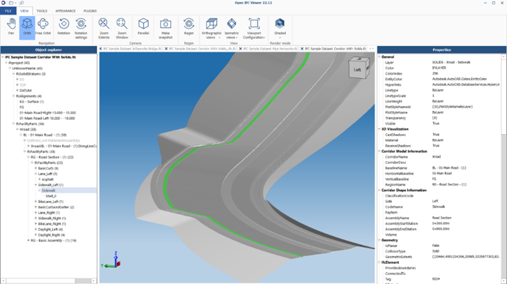
We can't now use IFC 4.3 since software providers are still working on developing and testing new import and export tools, so we will need to be patient. However, I would advise Civil 3D users to look into and play with with the formats that are currently supported. With the available tools, we can export objects from Civil 3D, but this does mean that most of the exported objects are IfcBuildingElementProxy entities and do not have defined types. Although this is not ideal, giving these objects the appropriate Property Data will give us the definition we require. Linking an IFC file created by Civil 3D into Revit can produce some effective effects, such as adding site drainage designs. We have talked with several of our clients about this subject, and we can offer solutions that will make the switch to collaborative working on BIM projects much simpler. For example, Symetri's Naviate tools for Civil 3D can offer an automated solution for collecting information from Civil 3D and AutoCAD and adding it to relevant Property Data Sets given to objects. Numerous properties, including chainages, sizes, lengths, and volumes can be automatically allocated and subsequently updated to account for changes made to the objects or their linked alignments or corridors.


Regardless of where you are in your BIM journey, we are always delighted to talk about workflows and new concepts. I have always found our customer interactions and discussions enlightening over the years, and my colleagues and I look forward to being challenged with fresh issues and ideas. I’m hopeful that some of you will accept the challenge to make use of IFC as an OpenBIM format on your projects, and maybe together we can define some truly fantastic advantages.  


Would you like to find out more about Civil 3D? At Symetri, we provide a wide range of Civil 3D training courses to help you improve project delivery, maintain more consistent data and processes, and respond faster to project changes. For more information, please contact us on 0345 370 1444 or info@symetri.co.uk.


Further information: 

IFC Overview: 

http://ifc43-docs.standards.buildingsmart.org/ 

IFC 4.3 Schema Definition: 

https://standards.buildingsmart.org/IFC/DEV/IFC4_3/RC4-voting/HTML/


What’s New in AutoCAD Electrical 2025

This blog will examine what’s new in AutoCAD Electrical 2025. Automatic Reports Enhancement In AutoCAD Electrical 2025, you can now cre...