When discussing with clients their Autodesk Revit issues and
how to use it as efficiently as possible, I frequently notice that they are
working on previous Revit versions. 2021 appears to be a common version among
recent clients I've spoken with. Given that the current release is 2023.1,
that's three updates since the version on which many projects are produced on.
These clients are frequently working on
large projects that span several years, have multiple consultants collaborating
on the project, and are the most difficult to upgrade, therefore are still
using an older version.
However, there are times when an incidental
issue arises, and I wonder to myself why. Surely you just need to… and then recall
that the solution is a feature that appeared in a later version that the client
is using.
So, I thought I'd take this opportunity to
highlight some of the new features that have been introduced in the last few
releases that can help alleviate some of the issues that are frequently
encountered.
SNAP MID BETWEEN 2 POINTS
The first that comes to
mind is the ability to snap to the middle of two points, which was introduced
in 2022. This has long been available in AutoCAD but was only
recently added to Revit. When drawing walls, sketching floor boundaries, or
moving and copying etc., you can access the snap overrides via the right-click
menu, with Snap Mid Between 2 Points being the first option on the list.
Alternatively, you can enable it with the
“S2” keyboard shortcut. You can even repeat it to get a quarter distance
between the points.
It should imply that fewer detail lines,
dimensions, or reference planes are required to accurately position objects.
SHEET REVISIONS
The ability to have multiple revision numbering
types was introduced again in 2022. This means that numbering systems with
different prefixes, such as the Provisional and Contractual revisions commonly
used in ISO19650 compliant projects, can be defined. When defining the
revision, the appropriate revision type can then be selected and applied to
sheets as needed. The revision sequence will reflect the various types.
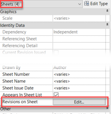
The ability to edit revisions on multiple
sheets at the same time is a fantastic addition to Revit 2023.1. Simply select
the sheets in the project browser and go to the properties palette and click
"Edit Revisions on Sheet" as usual.
A minor change that can easily be
overlooked if not highlighted, but it can save a significant amount of time
spent going through individual sheets to assign a revision.
PDF EXPORT
Once the revisions have been applied and
you are ready to issue them, PDF is the standard format. A built-in PDF printer
has long been a request for Revit. Again, AutoCAD has had these for many years,
and the difficulty of finding reliable PDF creators that aren't too expensive
for everyone who uses Revit has caused loads of frustration.
The issue was eventually
resolved in the 2022 release, but not as part of the print tool. Export PDF is
a new tool available from the export menu rather than the print menu. However,
it added some really useful functionality in terms of naming the PDFs.
The printed views or sheets can be combined
as multiple pages in a single PDF. 2023 gave the ability to control the order
of pages in the PDF, or as individual PDF files. As individual files, the
naming can be customised using parameter values from both the Sheets and the
Project Information, allowing for the automatic creation of complex naming
formats used in BIM compliant projects, including the current revision.
It can also detect the page size from the
title block, allowing us to batch-plot PDFs of all sizes and name them
correctly in a single tool built into Revit.
If you want this functionality in 2021 or
are interested in how it can be expanded in 2022 or 2023, please contact us and
enquire about Symetri's Naviate
toolset!
SHEET TOOLS
Sheets can now be duplicated in Revit, and
views can be duplicated as dependent or independent at the same time. This has
been a long-requested tool, and it is greatly appreciated.
Views placed on sheets can also be swapped
for a different view; there is no need to delete the view from the sheet and
place the alternative view separately, ensuring it is aligned with the previous
view.
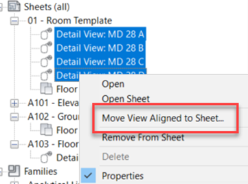
Views can be moved
between sheets in 2023.1 by dragging and dropping them in the project browser,
or by using the right-click menu, which allows the user to select from a
searchable list of sheets.
SCHEDULE TOOLS
The ability to split and
place schedules across multiple sheets is the first feature. Instead of having
to create and manage multiple schedules with filters, a single schedule can be
created and split across multiple views, much like a dependant view. Work in
the main schedule and changes will be reflected on all sheets as needed.
Another useful feature
is the ability to search for sheets, categories, parameters, and so on when
placing on views, pasting objects, or creating schedules. In this case,
dividing a door schedule across three sheets that are numbered or named
appropriately allows them to be easily found in the project's long list of sheets.
The ability to filter parameter types and
search for names when creating schedules saves time scrolling up and down the
long list of project parameters. A similar search function in the
Visibility/Graphics Overrides saves time as well.
Finally, the ability to filter schedules based
on the objects displayed on the sheet is an exceptionally useful addition. Creating
a sheet for individual rooms or apartments that includes a schedule of objects
for that specific space, for example, meant creating a separate schedule for
each room or apartment. Now, a single schedule for the entire project can be
created and placed on multiple sheets. The schedule will only list the objects
visible in other views on the sheet once it is placed on the sheet.
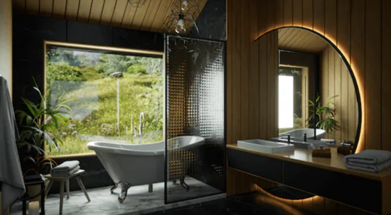
TWINMOTION
The last update I'll mention is not really
a Revit feature. Twinmotion from Epic Games is now included as part of the AEC
Collection in Revit 2023.1.
Twinmotion is a
standalone, real-time visualisation software package, powered by the Unreal Engine,
that can be downloaded and used as part of the AEC Collection licence.
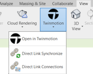
There is an Open in
Twinmotion tool in Revit 2023.1 that will create a link between the Revit model
and Twinmotion, which can then send updates from Revit to Twinmotion.
Additional items can be added to Twinmotion
to build the scene once the model is there. To make a model come to life, add
landscaping, trees, roads, people, cars, lights, furnishings, and other extras.
The Revit model's materials can be changed or substituted with new ones.
Many of these objects can also be animated.
Objects will be affected, causing trees and grass to sway in the wind and water
to ripple, as a result of the weather. Set the time of year to winter to see
snow falling in your model. People and vehicles can follow easily drawn paths
with speed and quantity controls.
Twinmotion then enables you to generate
high-quality images in photorealistic or non-realistic styles such as hidden
line and white models. Videos, 360-degree panoramas and videos, and interactive
VR presentations are also possible outputs.
Due to Twinmotion being a standalone tool,
it can also connect models from other versions of Revit. Therefore, if you're
still using Revit 2021 or 2022, you can still benefit from the Twinmotion addition
to 2023.
CONCLUSION
As Revit evolves, there don't seem to be
many big headline features that catch people's attention. This means that users
rarely feel the need to upgrade and instead prefer to work on older versions. However,
there are many new and updated features in each release, and some of them can
make a huge difference to the workflow on some projects - even if they are not
making headlines when they are released! If you're using an older version of
Revit, look for areas that seem time consuming or repetitive and notice if
there are any improvements in a newer release that could help. If you're
unsure, contact Symetri and one of our experienced consultants will gladly help
to see if there is a more efficient way of working in Revit, whether that
involves using a newer version or not.
I hope you found this article useful. If you need more help in Autodesk Revit, please contact SYMETRI by calling us on 0345 370 1444 or email us at info@symetri.com.


.jpg)


