Showing posts with label AutoCAD. Show all posts

Friday, 28 April 2023

Why Do We Learn? Considering CAD training

I thought I would try and give a little bit of insight into why we learn. I’m not referring to the physical bits, the synapses joining together to form memories which can be accessed at any time. No, I mean the actual motivating elements which gets us up and out of our seats and into a classroom. There are many reasons why we do this, and I will only cover a couple of them in this blog. I will also try and fit a type of learning to each motivation.

School

In the civilised world, we don’t really have the choice in whether going to school or to be home schooled, so I won’t be spending time covering this. I am more interested in when we have a choice in whether we learn or don’t learn, so we begin this a little later in life when we are gainfully employed.

Employee Placements.

A lot of companies today offer employee placements, this commonly comes in the form of the employee doing day release at University or College, helping gain some form of qualification which should be related to their job. I am all for this personally, but again, do many people actually have a choice in this? Especially in the case of apprenticeships, where this will be a stipulation rather than an option. If you get the chance of having this option offered to you, grab it with both hands. In my perspective, you are basically being paid to learn which is Nirvana in my mind.


Wanting new employment.

I have also been told that sometimes people don't stay at the same company for 25 years, as I have. So, if you are looking for a new job, do you even have all the necessary qualifications to even get to an interview stage? This is probably the hardest of all the motivating factors I find to go through. You read the job descriptions, and realise that you are not even close to getting to an interview for the role, so what do you do? You must weigh up whether you want to pay for a course on your own, so you get the necessary qualifications to make your CV pass inspection. It is however a gamble, and quite a big gamble for that. You really need to step back and have a think about your happiness, as well as your future. Is your current job really that unbearable, that you want to open your wallet? Realistically speaking though, unless you are looking for a complete career change i.e Mechanical Engineer to Cake Decorator, I'm not sure that it really is that necessary. You have fallen into a vicious circle that really is the whole point of me writing this article, your current role does not provide you with continuous learning and training, therefore you don’t have the skills to help you get another job. Why don’t you look at it like this, would you be happier in your current role if you got some training? Studies show that employees are much more content in their job roles if they get trained each year, it also demonstrates that the employer values you. If you ask for some training, great organisations will want you to do it.

This reminds me of a story, recently I helped train an engineering company that were really getting hit on productivity, nobody was innovating and basically, they were  operating the same way for the last 20 years. In a management meeting held, the subject of CAD training was raised, which would cost £20,000 for all employees to get some training that they desperately needed. The Financial Director posed the question "What happens if we spend on all this money on CAD training, and all of the staff armed with new skills get up and find another job". The Engineering Director's response in return was.

"What happens if we don't train all of these people and they stay?"

Your employer sends you on a training course

There are two different ways you can look at this, and which one you choose all depends on your outlook on life really.

  1. My employer values the work that I produce and recognises that my skills need updating for me to keep the best productivity, they are willing to spend money on me to aid in me achieving this.
  2. My employer thinks I am not very good at my job and implies I need to get some training, so I am not just taking up desk space, but so I can actually contribute to the company.

What is my answer to this? Am I a pessimist or an optimist? Do you know what? it doesn’t really matter which answer reflects your thoughts.
The result is the same, you get some training. However, the answer to the above question will have a huge impact on how much you will actually learn on the course.
If you attend the training, which your company has paid for, with a defeatist attitude, then know you probably won’t get much out of the training course. I have always maintained that I can teach anyone, whether they are young or old, with an intelligence level of either not so bright or extremely smart, a good teacher can teach anyone.
The one subset of people that I do struggle with however are those who think they know everything. Fortunately, I get very few of these kinds of people on my courses, and inevitably these types of people have just been sent on a course.

If your answer to the above statement was number 1, then you find online learning beneficial, as you will be motivated to actually take the time and use the online resources given resulting in you to get more productive, you would however gain more from attending some classroom training, as the teacher should be able to pitch the training to your level, as well as tailoring the course to put into perspective for your job. If your answer was number 2 however, then a classroom course would definitely be needed. Someone who isn’t motivated to attend a course, will not spend the time to learn from an online resource. They will always be too busy.

Remember every day is a school day!

If you would like to learn more about training at Symetri then please visit our website https://www.symetri.co.uk/training/


Monday, 6 March 2023

INFODRAINAGE STANDARD VS ULTIMATE

A drainage design software platform called InfoDrainage makes it possible to create Sustainable Drainage Systems (SuDS), Green Infrastructure, and traditional drainage systems. Both storm and foul networks are supported, permitting 1D and 2D simulations of multiple storms simultaneously.

InfoDrainage comes in two distinct tiers: Standard and Ultimate. InfoDrainage Ultimate offers all the features of the Standard edition in addition to 2D analysis and integration with Civil 3D. These features are discussed in this blog, along with some of the restrictions of the Standard version and, if available, any alternative workflows.

2D ANALYSIS

INFODRAINAGE ULTIMATE

A 2D analysis that shows the depth and speed of the exceedance flows in a plan view can be used to assess the flood danger to property or people during an extreme event.


INFODRAINAGE STANDARD

InfoDrainage Ultimate is the only product that offers this functionality.

CIVIL 3D INTEGRATION

INFODRAINAGE ULTIMATE

Using a special ribbon, which is available for Civil 3D 2020 and later versions; pipe networks, surfaces, and catchments from Civil 3D can be easily exported to InfoDrainage. Parts mapping can be used to choose the InfoDrainage connections and junctions that will substitute the Civil 3D pipes and structures after the network has been exported from Civil 3D as a storm or foul network. If there are numerous iterations between InfoDrainage and Civil 3D, this mapping will be remembered, and templates of this correlation can also be saved for use in other drawings.

In Civil 3D, the import procedure can build a new pipe network or update an existing one, making it easier to synchronise any changes made to the design. If the network in InfoDrainage includes any elements (such as ponds, swales, cellular storage, or open channels) without an equivalent structure or pipe in Civil 3D, those elements will be included in Civil 3D using polylines, feature lines, corridors, and surfaces. Multiple barrel connections are also supported and will appear in Civil 3D as multiple pipes.

INFODRAINAGE STANDARD

InfoDrainage Standard does not include a dedicated ribbon in Civil 3D. Although some InfoDrainage objects can be transferred using an intermediate file format, like AutoCAD, LandXML, or a shape file, it is frequently necessary to manually update and even model those objects in Civil 3D. Additionally, the Standard edition of Civil 3D only allows for manual updating of Civil 3D items (such as pipe diameters or slopes).

Using the Standard version necessitates exporting each object from Civil 3D to an intermediary file format and then importing that file from InfoDrainage, whereas the Ultimate version will export all the objects (pipe networks, surfaces, and catchments) and their properties simultaneously.


For pipe networks and surfaces, it is possible to use the LandXML format. A small inconvenience is that the Pipe and Structure names differ slightly between Civil 3D and InfoDrainage (e.g., "MH1" in Civil 3D vs. "MH1 (SWS)" in InfoDrainage, with "SWS" standing for the network name. Exporting to a CAD format is an option if LandXML does not produce the desired outcomes for the pipe network. This will result in the pipe network being exported to AutoCAD as a 2D polyline, requiring the creation of the pipe network in Civil 3D and the manual entry of the appropriate levels, pipe, and structure sizes.

InfoDrainage Standard does not allow straight import of civil 3D catchments. The Civil 3D model must be exported to an AutoCAD format prior to importing the catchments from that file. Since the catchments will be generated in InfoDrainage from polylines, the catchment names and runoff coefficients must be manually edited to match the values of the Civil 3D catchments.

It is possible to create new objects or change existing ones when importing an InfoDrainage file into a Civil 3D drawing that already exists. The diameters, slopes, and other dimensions of current pipes and structures can all be updated using this. A Civil 3D network can be modified to match the InfoDrainage file by adding new branches or removing old ones. This is not feasible with the Standard version; you would have to manually compare the two networks to look for those changes.


Similar to how you would export them, pipe networks and surfaces can be imported into Civil 3D using the LandXML file. The LandXML file does not contain stormwater controls (such as ponds, swales, cellular storage, etc.) or non-pipe connections (such as channels), so they must be imported separately. They can be imported as 2D polylines from Civil 3D using a shape file. The objects would then need to be modelled using Civil 3D tools. They are brought immediately as 3D objects using feature lines and surfaces by the InfoDrainage Ultimate ribbon.

Using a shape file, catchments can be imported into Civil 3D as 2D polylines. You then need to create each catchment from a polyline, rename them, assign a structure, and update the runoff coefficient using the values from InfoDrainage.

This video provides a quick comparison of these tasks performed in InfoDrainage Standard and Ultimate, or just in InfoDrainage Ultimate if no other workflows are available for the Standard version.


Do you need more help in Civil 3D? Take a look at our wide range of Civil 3D courses here. Alternatively, please do not hesitate to contact SYMETRI  on 0345 370 1444 or email us at info@symetri.com for more information. 


Saturday, 8 October 2022

What Is a Suitable CAD Workstation That an Architect Should Consider?

There is no doubt that there are some amazing computer-aided design (CAD) software solutions and toolkits available in the Architecture, Engineering, and Construction industries today, including AutoCAD, Revit, and Symetri’s own solutions like Naviate.

Architects are now more than ever, able to present some impressively detailed models to succeed in winning businesses, advance their business, and set an excellent example.

When working with new prospects, there is often a key "proof of concept" stage that necessitates being able to effectively demonstrate the final results before any agreement is made with a new client, much alone before any construction is started.

This is especially true within the building design stage in architecture, as well as many similarly challenged design firms. A detailed model is a ‘must have’ for clients on almost every project of this nature, whether it be for obtaining planning permissions, meeting sustainability requirements, or simply showing the homeowner what will be a lovely and well-thought-out design on the project for which they are investing so heavily.

Therefore, it makes sense that the industry depends so heavily on companies like Symetri and Autodesk to create the software tools required to accomplish all of this and more.

But with all this powerful CAD software at our disposal, can we really use it on just any computer?

It's crucial to make sure your hardware matches the software requirements if you want to offer the results you really desire. At Symetri, we work hard to give our customers the greatest and most up-to-date hardware available, customised to all of the CAD programmes we support, as well as many others that make use of this technology. When showcasing 3D models in Revit, creating bespoke housing models in AutoCAD, or even creating client logos in other applications like Adobe Creative Suite, we want you to be at your very best.

In light of this, I've suggested one of our top sellers that is perfect for Architects and designers alike, in creating the greatest possible 3D models that render intricate textures and visuals to impress clients.

Are you an Architect or a designer seeking for a strong, portable, sturdy CAD workstation, with a lovely and high-quality finish that you can use to show clients your designs?

If this describes you, the HP ZBook Studio G9 16" Mobile Workstation might be the perfect fit for you.

HP ZBook Studio G9 16″ Mobile Workstation


Top specs:

  • Intel Core i9 (12th Gen) 12900H / 2.5 GHz (5 GHz)
  • 32 GB DDR4
  • 1 TB SSD – NVMe
  • NVIDIA RTX A3000 12 GB GDDR6 SDRAM
  • 16" IPS 3840 x 2400 (WQUXGA) @ 120 Hz
  • 6-cell - up to 9.5 hours

Why do we recommend this?

  • Blindingly fast CPU performance, with options going right through the intel range to the latest i9 models that offer multiple cores for CPU-Rendering.
  • Up to 32GB RAM which allows for a generous amount of multi-tasking without any of the performance lag.
  • Multiple GPU options available to suite a budget or for best performance such as the latest nVidia RTX A3000 with more than enough GDDR memory to support an array of applications, as well as faster clock speeds for superior GPU-Rendering and precisely detailed textures.
  • A beautiful display to complement the above with a configurable options for full HD WLED / OLED display options across a 15.6” or 16” display.
  • 512GB or 1TB NVMe SSD high speed storage as standard, with additional storage capacities also available.
  • Impressive battery with on average up to 9.5hrs, with a fast-charging cable that can replenish the battery to 50% in as little as 30 minutes.
  • HP Workstations use hardware that benefits from ISV approval (Independent Software Vendor) by Autodesk, giving you the peace of mind that this has been tested and approved at the highest level.
  • All our CAD workstations are supplied with 3 years of on-site warranty, meaning that you can rest assured that unlikely issues should they occur will be resolved quickly by an engineer visit.

In addition to this, Symetri has produced a CAD workstation recommendation guide which offers more options based on your requirements: https://www.symetri.co.uk/campaigns/cad-workstation-recommendations-guide.

If you would like a personalised bespoke recommendation tailored to you, please contact SYMETRI by emailing us on info@symetri.co.uk or calling us on 0345 370 1444.

Saturday, 23 July 2022

On-Demand | What’s New in AutoCAD 2023

AutoCAD is computer-aided design (CAD) software that architects, engineers and construction professionals rely on to create precise 2D and 3D drawings.

This On-demand webinar explores new features of AutoCAD that will improve the user experience, collaboration and automation processes.

On-Demand Webinar | What's New in AutoCAD2023?

Webinar Agenda:

  • Changes found in full version
  • Changes in the LT version
  • New features
  • Updated workflows
  • Automation & Scripting
  • Express tools
  • Lack of automation in LT
  • AutoLisp vs Scripts
  • Creating AutoCAD scripts
  • Creating Lisps
  • Using VSCode to create Lisps
  • Running and debugging scripts

Interested in learning more about AutoCAD? Take a look at our range of AutoCADcourses ranging from AutoCAD essentials to more advanced training such as AutoCAD 3D Modelling.

Alternatively, please contact us on 0345 370 1444 or info@symetri.co.uk


Friday, 10 June 2022

AutoCAD training courses “Can I put the area of a room in a table?”

 As an Application Specialist with over 25 years of training Autodesk applications, I have recently noticed there has been a growing interest from delegates attending SYMETRI’s AutoCAD training courses to advance their skills with AutoCAD Beyond the Basics and the AutoCAD Advanced courses.

Why are more learners attending more advanced course?

Over the past months, I asked my students why there has been an increased interest in more advanced AutoCAD training courses.

The most common answers, is that their company has reached a plateau, the safe known workflows are not efficient anymore, many CAD drafting staff have retired and the time has come to refresh and reskill to advance the business to the next level.

I discovered the group dynamic to be extremely exciting in the Beyond the Basics and Advanced course, as I notice long time CAD users look at new features and workflows to adapt and apply to their needs in the design office. Our follow-on courses are very much a hands-on skill building experience.

“Can I put the area of a room in a table”

During these more advanced training courses, I tend to describe features that will streamline a workflow. For example, when I trained a group of delegates from the world of space planning, where they asked: “Can I put the area of a room in a table?” The answer being “yes”, allows us to discover the workflow to achieve this goal.

 First, we looked at the boundary command.


We then picked a point inside a room using the Object type as Polyline.


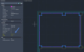
This created a closed polyline bounding one of the rooms. There is an entry which shows the Area and Length in the properties under Geometry. Using that information, we can populate given cells in a table.

Over in Paper Space we created a simple table to display Room Name, Room Perimeter and Room Area. In that table, we double clicked on the data cell under Room Perimeter and selected field in the Data menu.


Select object on the left field names in the field dialogue box, and then select the polyline. You can select the polyline model line even when you are in Paper Space.

We need Length to describe our room perimeter and Decimal for format.

In Additional Format we used a conversion factor of 0.001 to convert our millimetres unit size to meters for our table entry.

This gave us a value that represented Metres in Length for the perimeter of the room or boundary that we created. This value is dynamic so if you change the boundary, it will update the table field value.


Use the same procedure to extract the area value from the polyline and put in the table.

AutoCAD Training courses

We offer a wide range of AutoCAD Training courses, please visit our website for more information: https://www.symetri.co.uk/training/autocad-training-courses

AutoCAD Essentials - This course covers the essential core topics for working with the AutoCAD software, starting with a few basic tools expanding to more advanced ones. Find out more: https://www.symetri.co.uk/training/training-courses/autocad-essentials

AutoCAD Beyond the Basics - This 2-day course will help you explore more advanced tools and techniques to help you work smarter. Explore the full course content here: https://www.symetri.co.uk/training/training-courses/autocad-beyond-the-basics

AutoCAD Advanced - Customising and managing AutoCAD to suit your design application is a great way to increase your productivity. This course teaches simple but powerful customisation techniques and advanced AutoCAD tools. Explore the full agenda here: https://www.symetri.co.uk/training/training-courses/autocad-advanced

Testimonial:

The course has been really helpful, informative and enjoyable - often training can be boring but Geoff made it easy for us to understand and relevant to the work we are doing. I can't wait to utilize the skills I've learnt & am also looking to book the next course - only if Geoff is teaching!” Natalie W


Tuesday, 29 March 2022

What’s New in AutoCAD 2023?

Our Application Specialist Geoff Alder provides an overview of the new features and updates in AutoCAD 2023.

1. Traces

The traces feature found on the collaborate tab monitors and logs redline revisions.


Opening the traces pallet in the first instance shows that there are no traces in the drawing.


If we use the Markup Import feature, we can then overlay a red line markup. This can be an image file i.e., jpeg, png, pdf. I have used a pdf with a simple redline markup on this drawing.

Clicking on Markup Import brings up the dialogue.

The Markup Import has discovered the two redline markups. One in text form and one in hand sketched detail. We can then extract the details and have them on the drawing as a markup.

The markup is now listed in the traces pallet, providing users with a time that the redline edit was added to the drawing.


2. Copy Base

The copy base feature in AutoCAD 2023 is efficient in a workflow. It provides a basepoint in the first instance in the lower left extreme of the geometry.


3. Polylines

Polylines are often used to create boundary areas and closed lines. In plotting vertices to create the polyline, we have to continue in one direction because the vertices are numbered to describe the direction of the polyline.

If we add a vertex at the last vertex, this provides an additional vertex which increases the polyline length. If, however, we add a vertex at the start of the polyline, we are adding a new vertex in position two and not adding to the length of the polyline. This means we can right click on the vertex on either end and choose “Extend vertex” which will extend the polyline at that point. This can be a great time saver in creating clean and efficient polylines.

[Can we have a screenshot]


4. Display - View Tab

With the view to display options, we can now detach a View Tab in AutoCAD 2023 and have it floating; thus allowing it to be moved to a second monitor if required. The view also has its own command line making it easier to focus on a view and have the option to input commands in the same line of sight.

[Can we have a screenshot]


5. Display - FASTSHADEMODE

On display in AutoCAD 2023, we see a new command called FASTSHADEMODE. This takes advantage of newer GPU to provide a superior illuminated 3D view.

[Can we have a screenshot]


Overall, the new features & updates in AutoCAD 2023 are stable and can be used as part of everyday workflows.

Watch the video below to see these new features in action:

https://youtu.be/ldmYQ6nMnZw (embed)

To learn more about AutoCAD, please visit our product page or contact us by email  info@symetri.co.uk or telephone 0345 370 1444.

Monday, 10 January 2022

Webinar Recording | #WorkSmarterWednesdays | Create and Collaborate - Integrating AutoCAD with Autodesk Build

 https://www.youtube.com/watch?v=vHDfPE7KYfs

This special edition of our #WorkSmarterWednesdays webinar series includes our partner Autodesk, discussing how integrating AutoCAD with Autodesk Build can make the sharing of drawing changes simple.

Webinar Overview

Being an architect, engineer, or designer, means the process of actioning changes to CAD drawings from contractors can be a difficult task. This is due to those working on site not always having access to the necessary tools to help their design counterparts with updates to the actual drawings. This results in changes being captured in the form of handwritten notes or marked up PDFs, creating more work for both those on site and the design teams.

During this webinar from our partner Autodesk, you'll learn the benefits of digitising drawing changes, as well as how this can be achieved by integrating Autodesk Build with which AutoCAD based authorising tool you’re using.


Webinar Agenda

  • Share documents with the entire Autodesk Construction Cloud
  • Host digital versions of drawings that are accessible from any device
  • Assign tasks to team members
  • Mark changes, tag and notify design reviewers
  • Create a single source of truth for everyone on a project

For more information, please get in touch with us by emailing info@symetri.co.uk or call us on 0345 370 1444.


Thursday, 9 December 2021

Factory Design Utilities – 2D & 3D Factory Layout and Optimisation Solution

As part of the Product Design & Manufacturing Collection not only do you have access to standard tools such as AutoCAD and Inventor you also have Factory Design Utilities.

Factory is Autodesk terminology to determine if Autodesk software can assist in a global change in the design environment as opposed to adopting an individual one into designs and processes.


Do you design in 2D and model in AutoCAD 3D or Autodesk Inventor?

Many companies have the Manufacturing collection but don’t know they have the Factory suite which enables them to round trip their 2D design from AutoCAD to Inventor or Vice-versa.

With factory Design Utilities, your Design Engineer can create 3D assets in Inventor, take them into AutoCAD and manipulate them in 2D.

If your contractors need to collaborate their Revit Models or Navisworks documents with your 2D/3D models they can do this in Factory Design Utilities as part of the Design & Manufacture Collection.

Factory Design Utilities can assist in not only designing factories, but also Design Co-ordination, Playground Design, Petrol Stations, Process Analysis and many more.

Watch our on-demand webinar to learn more about and Factory Design Utilities.

For more information or to discuss your requirements further please contact Symetri.

Wednesday, 26 May 2021

Displaying terminal information in AutoCAD Electrical

In this blog article, we are going to take a look at how to show terminal information within an electrical design in AutoCAD Electrical and how to extract this information for device termination, display cable/wire information and to help later processes such as procurement.  

You can display Terminal information within a schematic layout.  From the icon menu select the terminal symbol and assign the relevant information to that terminal such as installation/location code, tag strip identification, terminal information and catalogue information.

The information can then be extracted into a graphical or table layout on a terminal drawing within the electrical project. This layout is used to show cable/wire information, device information, internal jumper layouts and catalogue information. Additional terminal accessories can be added by assigning the catalogue information. Accessories can include including terminal holders, spacers and covers.


Note: To ensure the component is displayed in a graphical layout all catalogue information will need an associated block defined in the footprint database. 

If you are wanting to use a specific component that does not exist within AutoCAD Electrical you can create your own symbols and footprints. Select the symbol builder feature and choose the specific type of component you require such as parent component, terminal or panel terminal.

For further information on the benefits of using AutoCAD Electrical for your electrical design, contact Symetri to arrange a consultation with one of our electrical specialists. We also offer scheduled AutoCAD Electrical essentials training, as well as bespoke training tailored to your requirements .


Friday, 24 January 2020

Training learning paths for Civil Engineers


Civil engineering involves a variety of fields, such as surveying, geospatial analysis, transportation, infrastructure design or drainage. Getting trained in all those areas can be a challenging task, so you may work in a specialised area, or over time develop your skills in a number of areas. This article should provide you with some guidance on how to acquire the relevant skills you need for your role or areas of interest, based on your current level and your area of specialisation.

As a starting point, I would suggest Excitech’s AutoCAD Civil 3D, Fundamentals course, which provides a thorough introduction to Autodesk Civil 3D. This includes hands-on exercises on surface creation from a topographic survey, road design, cut and fill volumes, pipe networks design and drawing production tools. Alternatively, new users can opt for the AutoCAD Civil 3D, Foundation Skills course instead. This is a reduced version of the Fundamentals to be taken as the basis for one of the follow-up courses that specialise in a particular area.

If you are involved in land surveying, you can learn how to download and process survey data inside Autodesk Civil 3D by attending our AutoCAD Civil 3D, Working with Survey Data course. If you are interested in geospatial analysis, the AutoCAD Map 3D, Essentials course will demonstrate how to create, manage, and map data.

For engineers working in Highway Design, AutoCAD Civil 3D, Transportation Design will steer you through the more advanced aspects, like applying standards, superelevation, roundabout design, road widening, and road rehabilitation. In addition, the Autodesk Vehicle Tracking course will give you all the tools you need for vehicle swept path analysis.

To help you in the design of drainage and utility networks, the AutoCAD Civil 3D, Drainage Design course will detail how to use Autodesk Civil 3D in conjunction with other design tools such as MX and WinDes and provide a realistic workflow from the design to the analysis and presentation.

Another piece of software that every civil engineer should know is Autodesk Infraworks. Autodesk InfraWorks for Civil Engineering will show you how to create preliminary designs and sketches that illustrate initial proposals to others involved in the project and how to create presentations of those designs in a photorealistic environment. Related to this last aspect, AutoCAD Civil 3D, Design Visualisation demonstrates how you can export Autodesk Civil 3D design models into 3ds Max Design to create high quality visualisations that can be utilised in the exploration of design alternatives, visual simulation and public consultation.

Aimed at Project Managers, the AutoCAD Civil 3D for Project Managers course provides an overview of the functionality of Autodesk Civil 3D, covering BIM, the use of basic modifying and query tools and how a project in Civil 3D is typically configured. There is also guidance on working in a multi-discipline project and in a collaborative environment using Revit and Navisworks.

To underpin your skills, you may want to consider the Autodesk Professional Certification Exam, which is available for a number of Autodesk software solutions, including Civil 3D.

Explore our full range of Civil 3D training courses here:


Tuesday, 17 September 2019

Creating A Custom Linetype Within AutoCAD

In this blog, with the assistance of the Express Tools, I am going to take you through how to make two different types of Custom Linetype, sometimes referred to as Complex Linetypes, within AutoCAD. The first will contain text and the second will contain a shape.

COMPLEX LINETYPE WITH TEXT

The first Linetype containing text will be called POWER and will look like the image shown below:

To begin, within an AutoCAD drawing, set the current layer to 0.

Load the Single Line Text command and set Justification to MC (Middle Centre), Height to 1 and Rotation to 0. Type, POWER.

Now draw a Line from the Insertion Point of the text as shown below. This is to ensure it is drawn central, vertically:


Using the Lengthen command, set the Total Length to 1. Move the line, if required, closer or further from the text then mirror it so it appears as below: 

From the Express Tools Tab on the ribbon expand the Tools Panel and select Make Linetype:


In a location of your choice create a file called My Linetypes. For Linetype name, type POWER and 

for Linetype description, type: The word POWER within a line.

When asked to specify starting point for line definition, pick point A and for ending point pick B as shown below:

At the Select Objects prompt select both lines and text.

After pressing Enter / Return, the command line should say the following: 

Linetype "POWER" created and loaded.


To demonstrate this has worked, create a new layer and assign the POWER Linetype. , then draw a Line. If all has gone to plan you should see something like this.


Note: When AutoCAD is installed, it should load the Express Tools by default. If for any reason these are not visible within the rRibbon, type EXPRESS TOOLS, and they should appear.

COMPLEX LINETYPE WITH SHAPE

The second Linetype containing a shape is a little more involved and has an essential step at the end. It will be called, HEXAGON and will look like this:

To begin, within an AutoCAD drawing, set the current layer to 0. Using the Polygon command draw the following shape. 6 sSides iInscribed and a Radius .5.

Draw lines on either side, 1 long.

From the Express Tools Tab on the ribbon expand the Tools Panel and select Make Shape.


In a location of your choice create a file called HEXAGON. For Shape name, type HEX, accept default resolution. When asked to Specify insertion base point pick at point A as shown:

At the Select Objects prompt select all objects.

After pressing Enter / Return the following message appears on the command line:

Shape "HEX" created.
Use the SHAPE command to place shapes in your drawing.

Type Shape and press Enter / Return. Enter the name of the shape which is HEX. Place the `Insertion point’ in the same location as the Insertion Base Point (A) you previously specified, so the shape overlays the original drawn objects. Specify a height of 1 and a rotation angle of 0.

The reason for overlaying in this way is because when we make the Linetype we need to object snap to the ends of both horizontal lines. We cannot object Snap to a Shape other than its insertion point.

Within the Express Tools Tab on the Ribbon expand the Tools Panel and select Make Linetype.

From the same location you created the `My Linetypes.lin’ file select this file and choose Save. Say Yes to replace it. For Linetype name, type HEXAGON. For Linetype description, type Hexagon shape within a line.
Note: The procedure above doesn’t actually replace the `My Linetypes.lin’ file at all. It simply combines the Linetypes, POWER and HEXAGON into the same file. This you will discover later.

 When asked to Specify starting point for line definition pick at point A and for ending point pick B as shown below:
At the Select objects prompt, select the Shape only. (NOT THE LINES UNDERNEATH)

After pressing Enter / Return, the command line should say the following:
Linetype "HEXAGON" created and loaded. To demonstrate this has worked, create a new layer and assign the HEXAGON Linetype. Draw a Line. If all has gone to plan you should see something like the image shown on the right.

LOADING A COMPLEX LINETYPE WITH SHAPE WITHIN A DRAWING FOR THE FIRST TIME

This procedure would typically be carried out within a Template File to remove the need to do this in every new drawing.
Type COMPILE and within dialog Box select the name of the Shape (.SHP) file. HEXAGON.SHP


After, select Open, the following similar message should appear within the command line:
Compiling shape/font description file
Compilation successful.  Output file C:\Users\TerryD\Desktop\HEXAGON.shx contains 115 bytes.

As you will see it has created, HEXAGON.SHX file.

Type LOAD and within the Dialog Box select HEXAGON.SHX file from the location referred to in the previous message.

Now type SHAPE. At Enter Shape name, type HEX then pick somewhere in the drawing to place it, and specify height = 1 and rotation angle = 0. You can delete this after insertion.

To demonstrate this has worked, create a new layer and load the HEXAGON Linetype from the file called, My Linetypes, we created earlier, and then assign to the layer HEXAGON

Draw a Line. If all has gone to plan, you should see something like this.


Hope you’re successful in carrying out the steps above, on creating  Complex Linetypes, within AutoCAD and it has proved useful.

If you would like more information on the AutoCAD software, feel free to get in touch by emailing marketing@excitech.co.uk.


What’s New in AutoCAD Electrical 2025

This blog will examine what’s new in AutoCAD Electrical 2025. Automatic Reports Enhancement In AutoCAD Electrical 2025, you can now cre...