Wednesday, 15 July 2020

Civil 3D Property Set Secrets

Civil 3D’s Property Sets have been around for a while now, and if you’re working on a BIM project,they are fundamental for adding additional asset data to both Civil 3D and AutoCAD objects.Property Set data will be included with objects when a model is exported to IFC or Navisworks. 

Here are some tips and examples to help you make full use of Property Sets in Civil 3D.

Labels and Tables
Property Sets can be used for adding annotation to Civil 3D drawings. When Property Set data is added to a Civil 3D object, its fields are made available in the Label Text Component Editor.


We can also add the same information to Tables, although the Property Set data isn’t exposed in the Table Editor. To addthis data to a Table Column, type the required field into the Component Editor as follows:

<[PS:Pipes:Bedding(CP)]>

Where Property Set denotes Property Set data, Pipesis the name of the Property Set, and Bedding is the name of the field. The (CP) is a formatting field which in this example denotes Capitals Preserved.


Using Pick Lists
For many types of data, we would want to restrict the user to a specific list of possible values. This can be achieved by adding a List to our Property Data.

In the Style Manager, turn off the Filters.


This gives us access to more features, one of which is the List Definitions.


In this example, we’ve added a new list for Pipe Bedding. The list “Applies To” setting must be assigned to “Manual Property Definition.” 


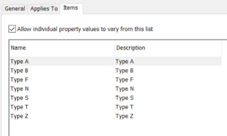
Items can then be added to the list as required.


In the Property Data set, the list can be accessed by adding a manual property, and then choosing the “List” option for the Type of field.


Notice that there is a Formula field whose source is set to the new Bedding_Class property. This is required as a List field and cannot appear in a Civil 3D label, but the Formula field will do. 


After adding this Property Set to Pipes in the drawing, the user can select a value from the defined list.


VBScript in Formulas
Complex data fields that can read properties of objects and manipulate data can be created by using VBScript in formula fields. One of the issues you may find is knowing what commands are available to you, but the VBScript Code helper is empty.


The information that populates this is saved in an XML file. Since the Property Set feature has been “borrowed” from AutoCAD Architecture, the definition file is still available. It can be downloaded from this link:


Copy the file into C:\Program Files\Autodesk\AutoCAD 20XX folder.

The helper will then be populated as shown:


VBScript can be used to retrieve data from Civil 3D objects by making use of the Civil 3D API.

Here’s a straightforward example that creates a field that displays either a manhole diameter or length x width, depending on whether it is a circular or rectangular structure.

RESULT="--"
On Error Resume Next
Set oApp=GetObject(, "AutoCAD.Application")
Set oCivilApp=oApp.GetInterfaceObject("AeccXUiLand.AeccApplication.13.0")
Set obj=oCivilApp.ActiveDocument.ObjectIDToObject([ObjectID])
If obj.BoundingShape = 1 Then
Result = CStr(obj.StructureInnerDiameterOrWidth*1000)
Else
Result = Cstr(obj.StructureInnerLength*1000) + " x " + CStr(obj.StructureInnerDiameterOrWidth*1000)
End If


The Civil Application must be set to the correct value depending on the version of Civil 3D you’re working on.

The following codes are valid for these versions: 
2018 - 12.0
2019 - 13.0
2020 - 13.2

To use the code snippet shown above, the Object ID of the structure must first be defined as a property field using an Automatic property definition.


Property Set Commands
Aside from using the Manage ribbonto access the Property Set definitions, there are several commands you can benefit from using on the command line:

AECPSDAUTOATTACH OFF or ON – automatically assigns property sets to relevant objects
PropertyFormatDefine Calls up the Style Manager interface
PropertyData Combines some of the commands in a command line version
PropertyDataBrowse A useful command to see where property data has been assigned to objects
PropertyDataEdit Edit property data on selected objects
PropertyDataExt List and edit attached property data on a selected object
-PropertyDataEdit Scriptable command line version to edit property data on selected items. 
PropertySetDefine Calls up the style Manager with Property Set definitions
PropertySetClean Removes a Property Set from object types to which it no longer applies
PropertySetAccess Edits the visibility and permissions of Property Sets. Used by the IFC Export –Do not use this command!
PropertySetDefSync Do not use this command!(Except perhaps as a last resort if your Property Data is really messed up!)
PropertySetDump Dumps the Property data and other information to the screen
PropertySetDefMerge Combines Property Set definitions
ExportPropertyData Exports Property Data to a Microsoft Access database

I hope you find this post useful. For other useful information and blogs on Civil 3D, visit our website here.

If you require any further information on Civil 3D, please feel free to get in touch by calling us on 01992 807 444 or emailing info@symetri.co.uk.

Wednesday, 3 June 2020

Archibus V.25.1 Review

Every year Archibus releases their latest version of the CAFM Software.

Follow us, as we look at the new features within V.25.1.

Refreshed Web User Interface
The first thing you will notice when you open the new Archibus version 25.1 is the refreshed web user interface. The old process navigator makes way for the more dynamic side bar navigation. While users will recognise the hierarchy layout, the side bar expands across the screen as you navigate and is organised with renamed modules and applications (For example, Corrective Maintenance replaces On Demand work), split into quick access shortcuts and full navigation and now shows navigation icons to help you quickly make your selection.


The side bar navigation also houses the new user Favourites function, simply click on the star in a view or report and it will appear in the list. The side bar also includes a relocated view search function which continues to offer users quick access to lost views anywhere across Archibus. The side bar can be collapsed to open up the screen size for your work, leaving a thin bar of icons visible for when you need to return. The new user interface includes nice little touches such as a glorious spinning wheel for longer page loads, which has been long awaited.


There is also the new left alignment of standard view buttons like Add, Save and Delete, which might leave more experienced users clicking thin air over on the righthand side of the screen.

The existing Home Page navigation can be used in conjunction with the side bar, although there is a push towards these being used as more graphical dashboard navigations. The Tasks option has been removed and the default pages no longer include task links as standard. Home Page navigations still offer organisations a great way of tailoring the product for different groups of users and presenting heads-up display information and we see it playing an important part of customer facing systems.


The new look extends across into the updated workplace function, with simple graphical screens optimised for touch screen use. It is now easily configurable to your organisations service catalogue, branding, with controllable menus and graphics. Set up is managed in the Service Desk role with a new view with lots of great options including the addition of request specific guidance so you can make sure users know exactly what they need to do. Fields and options can be turned off for each request type which helps keep the request forms clean and simple.

The workplace function continues to offer excellent visibility of your valuable data by providing easy to access tools such as finding rooms, employees, or organisational areas as well as visibility of the floor plan graphics.


The Mobile Maintenance App
The mobile maintenance app has seen some fantastic improvements through the redesign of the interface. The new screens have been reworked very much from a user’s perspective to simplify how your workforce record their work activity. Screens include large function buttons for starting, updating and completing work, helping users log work more quickly and with fewer clicks. Starting a job prompts the user to select a work type which automatically begins running the timer for the work entry and time is accurately recorded with minimal effort.  Basic forms prompt the user at each step of the main workflow and big action buttons like ‘Resume’ on the main menu will mean you can quickly carry on with work you’ve already started. We are confident that users will love the new app spending less time on their mobile and more time delivering services.


The Space Console
It’s good news for those who use Archibus to manage their space, as changes in V.25.1 are focussed on the Space Console administrators view. The view has been re-arranged and condensed to include new functions while retaining a large viewing panel. Floors are selected using the new smart search box, which provides quick access to your floorplans while taking up less space on your screen. Selecting a search result displays the floorplan automatically which now feels quick and responsive. More complex filters can still be applied now using the Advanced Search function, with increased search options that allows organisations with a variety of data structures to use the function to find specific spaces.

The viewing options have been re-organised and given nice new icons and menus for controlling the display and highlight querying of both 2D and 3D plans. You will soon get used to them and start enjoying the extra screen space they give you!


System Administration
Behind the scenes of the CAFM software are big changes too. The Archibus Connectors tool, for years has been the go to place for system integrations, and is now accompanied by a set of true REST APIs. These can be used to quickly establish data flows between Archibus and other applications or data sources. The APIs cover; generic data access – for access and update from anywhere with Archibus, service desk – for integrating with other service management solutions / processes, employee locations – for synchronising data staff locations with ERP solutions etc. We are particularly excited about the service desk API and how it will simplify the connection of request workflows between different platforms.

Find out more about ARCHIBUS here: https://www.symetri.co.uk/ARCHIBUS

And talk to us about your CAFM software: https://www.swg.com/excitech-swg/


Wednesday, 20 May 2020

#OrbitFromHome: 10 at-home learning resources from SketchUp


We’ve all had to adjust to working from home, which means keeping in touch with colleagues, family and friends remotely. So, to keep you occupied and to help develop your SketchUp skills, we’ve rounded up top 10 learning resources from Trimble that you can benefit from while you #OrbitFromHome.


  1. Learn the SketchUp fundamentals from this self-guided course. Reminder: it’s free and subtitled in more than 100 languages!
  2. If you’re more experienced at SketchUp, dive into the Skill Builder video playlists and polish up your skills.
  3. Discover the Podcast, SketchUp Talk! A great companion to listen to while you’re orbiting away on the axis.
  4. Still tight on time while working from home? In under 60 seconds, explore these Quick Wins packed with powerful skills.
  5. Curious about how other professionals are using SketchUp? Learn from the best and brightest in our customer case studies.
  6. See it all live! Tune in to live model challenges - every Friday at 12 pm MT. Don’t have time to catch it live? Watch the recordings.
  7. Try out some of the other products you have access to as a SketchUp Pro Subscriber! Spend some time learning LayOut, share projects with Trimble Connect, model online with SketchUp for Web, or check out SketchUp Viewer for your mobile device!
  8. Looking for new ways to customise your workflow? Explore our Extension Inspections to find the perfect plugin for you.
  9. Tired of dressing up with nowhere to go? Recover your sense of style by learning how to make (and personalize) your very own 2D Component!
  10. *BONUS!* Share how you’re staying inspired over the next few weeks by tagging your designs with #OrbitFromHome for a chance to be featured on Trimble’s social channels!
Whether you’re using your free time to become more proficient and efficient at SketchUp, getting workflow tips from other SketchUp users, or leaning because of your love of design during these times, we hope you’re staying healthy and taking care of yourself and your loved ones.

For further help with SketchUp, don’t hesitate to get in touch with us: https://www.symetri.co.uk/products/sketchup-pro

Monday, 4 May 2020

4 Things you Need to Know About PC as a Service (PCaaS)

As we’ve seen over the years, technology is constantly evolving, everywhere, and the way in which people are working is also changing.

According to ZD Net1, traditional CAD computer sales are declining and will continue to do so for the next decade or more. This is because more and more people are beginning to use mobile devices for their work instead. Why? Because they are easier and cheaper to upgrade and purchase.

However, with the recent emergence of the PC as a Service (PCaaS) model which emulates the subscription model now prevalent in the technology world e.g. mobile phone upgrade plans etc, PC and CAD computer sales are less likely to decline for several reasons. These include: 

1. Simplicity


Within the architecture, engineering, construction and manufacturing industries, the CAD software used on a daily basis needs to be run on a CAD computer with enough power to handle the demands of this software.

It is common for people to purchase the CAD software from one supplier, the CAD workstation from another and support from another also. With PCaaS, the need to use different suppliers is eliminated as it allows you to procure these assets through one, simple subscription.

2. Lifecycle Management


In addition to being able to procure your CAD workstations, software and support as a subscription, it also takes away the stress of managing these assets e.g. making sure that there are enough software licences, making sure that the CAD computer meets the demands of the software and checking that the software is installed and verified across every machine.

With the PCaaS model, this lifecycle management almost completely shifts to the supplier allowing you to focus on more strategic ventures.

3. Scalability
PCaaS allows organisations to easily scale up or down. For instance, whether you are taking on a new project and only need additional CAD workstations for a certain period of time, or whether you have increased/decreased your staff count, you can simply reduce/increase the number of devices you lease from the supplier rather than being left with a surplus of devices you may not ever need again.

4. Latest Technology at Your Fingertips
Most PCaaS terms are annual or over a certain period which means that every year or so, when your subscription is up for renewal, you will be given the option to upgrade to the latest software release and a more powerful CAD workstation, keeping you continuously up to date with the latest technology. This prevents you from holding onto ageing devices and  will eventually save you more money in the long run.

Earlier last year, Excitech launched its own PCaaS offering known as the “Excitech Design as a Service Package” which addresses the specific workflow requirements of construction and manufacturing sector businesses. Learn more about our PCaaS offering here www.excitech.co.uk/Excitech-Design-as-a- Service.

1 ZD Net https://www.zdnet.com/article/why-pc-as-a-service-is-the-next-big-thing/ (20th December 2018).


Friday, 24 April 2020

How to introduce Generative Design into your Workflows?


Welcome to the second part in this series of articles around Generative Design within the Manufacturing sector. The next local step, after setting the scene in the previous article https://excitech.co.uk/Insights/Blog/April-2020/Generative-Design-for-Manufacturing-Article-1, is to dive deeper into how you can look to introduce Generative Design into your current workflows.

The only product which currently includes Generative Design is Autodesk Fusion 360. However, do not let that put you off if you are an existing Inventor user. Most people these days will be utilising Inventor as part of the Product Design and Manufacturing Collection, which also includes access to Fusion 360. However, I would recommend you speak to your license Contract Manager to confirm this. But assuming you do have access to Fusion 360 as part of your package, you can simply download/install, then start to explore.

The first thing you will need to do, when approaching Generative Design. Is to consider your requirements, this can include things like:
  • Are there parts of the design which need to be kept, i.e. holes or clearance areas?
  • Are there manufacturing constraints? What manufacturing processes do you have access to?
  • Are there areas of the design where no material should appear or obscure?
  • Where are the constraints on the design, i.e. fixings or bolts?
  • Consider your objectives, is it light weighting or increased stiffness?
  • What loads is the design subject to, including misuse?
  • What materials are available?
Following this, you will need to generate some geometry in Fusion 360, to represent the above scenarios. So, if we take a simple example of a clevis bracket, as per the below, which needs to consider the fact that it will be bolted to a wall with a pulling force of 50N. Manufacturing considerations are access to 3 and 5 axis CNC, alongside Steel and Aluminium material stocks.


The geometry we need to create for this scenario, is perhaps not what you would expect. As you are effectively modelling the constraints of the problem, not the outcome geometry, which is more traditional. Therefore, for this example the modelled problem is going to be something like the image below.


Where the Green items are Preserve regions and the Red items are Obstacle regions. Put more simply, the Green areas are parts of the end design we must have, i.e. holes for the bolts to the wall and where the clevis will attach. The Red areas are regions where we do not want any material, i.e. clearance for bolt heads and tools, or where we need the outcome to have a flat bottom to attach to a wall.

Following on from this, it is a case of applying loads and conditions that the model will experience during its use. It is worth considering additional operating considerations at this point, to consider product misuse. For example, would you want the clevis bracket in this example to stand up to a side impact? Below you will see the loads and constraints required for our bracket in this sample.


Where Blue arrows are loads with direction of force, Green arrows represent Gravity and its direction on the part. The Padlock items are Fixed constraints applied to the component, in this example illustrating the points where the bracket would be bolted to a wall.

Now you need to make choices around how you want to manufacture the part, what materials you want to use and your study objectives.


At this point and prior to running a study and using up Autodesk Cloud Credits in the process, it is well worth doing a Preview. This will indicate where material will go and just as importantly where material should not go.


Once all the above has been done and assuming the Preview is looking sensible, with no material starting to form where you do not want it etc., then you are ready to run a study. At this point, you will be advised of your Autodesk Cloud Credit usage, at the time of writing this is 25 Credits per study run (with multiple outcomes). All the information will be uploaded to the cloud and processed accordingly. The Study option allows you to see the progress of outcomes during the process and investigate the differing results to compare results.

The below are some different examples from a single study, to highlight the differing manufacturing outcomes.


All study outcomes can be analysed and compared, to review how well they perform, alongside results based on the original objectives. These can be shown in different ways and the display of information can be focused on what are the important criteria for you and the study being conducted.


There could be different uses for this information, it can give you an indication of where to add/remove material from an existing design you have. It could be there to advise on a completely new design. Or you may want to directly use the generated 3D data. This data can be downloaded, upon completion of processing in the cloud in one of two formats: T-Spline or Mesh. You will be advised of your Autodesk Cloud Credit usage to do this; at the time of writing this is 100 Credits per download of a Generative Design outcome.


Once downloaded, this data can be used directly inside Fusion 360. Or the data can be exported from Fusion 360 or Teams. Or if you currently utilise Autodesk Inventor, then you have access to AnyCAD import, via the Autodesk Desktop Connector functionality.


Hopefully, this article provided a greater understanding of the workflow required with Generative Design in Autodesk Fusion 360; along with an introduction as to how you might include this alongside your current workflows in Autodesk Inventor.


If this is something you are interested in exploring further, then please get in touch by emailing us at info@symetri.co.uk


Saturday, 4 April 2020

What's New in Inventor Professional 2021

Autodesk’s experienced product, Inventor Professional 2021, has now gone live. This new edition has been improved in the four key areas below:
  • Performance
  • Modernisation
  • AnyCAD
  • Automation

Performance:

As with every release, Autodesk Inventor Professional has enhanced product performance to allow for greater speeds and capability. Below you will find a list of some of the key areas they have improved:


Modernisation:

Tools have been gradually updated in line with the modernisation of the product. This year is no different, with Autodesk updating tools such as Coil, Thicken/Offset, Frame Generator and Delete Face. They have also released the new dark theme to counter issues that come with the blue light and light theme exposure. 

AnyCAD:

The interoperability between Revit and Inventor Professional has been constantly reviewed. With this release, Autodesk have incorporated the ability for Inventor Professional to read Revit 3D data. What is great about this is that it is a live connection and allows Manufacturing and Architectural companies to work seamlessly using BIM.

Automation:

The ability to automate procedures is a constant feature with each update. This year pre-sets have been added to Frame Generator and drawing templates have been enhanced to improve this aspect. 

General Part Enhancements 

Some features in the part environment have been improved with the likes of now having the ability to window select multiple bodies. Previous versions would have made you choose this by selecting on them individually in the window. This will save users a vast amount of time considering it's a small tweak, especially when working in the woodwork environment. 

Another feature they have tweaked in the part environment is the unwrap tool, which now align to specific work planes. They have also enabled coplanar holes to stay rigid; this allows for holes to keep a set distance when creating the flat pattern. 

The flange tool in the sheet metal environment has been updated to now allow you to choose a reference face. This is good as it will reduce manual calculations when trying to match an exact angle.

Frame Generator Enhancements

All the tools in Frame Generator have been updated with the modernised theme to now allow it to be docked into the properties panel. This goes hand-in-hand with some much needed adjustments that allows for a smoother workflow. Firstly, the new zoom options which allows users to see the placement of a member perpendicular to the view. Secondly, you can also zoom so the member is fit to the view of the screen. Both options provide a great new alternative when aligning your member.

Further improvements to the notch tool include a follow on from the custom ‘I’ template in the 2020 version, with Custom ‘C’ and ‘T’ Templates. Improvements like this allow for the Frame Generator environment to become a more well-rounded tool. 

General Drawing Enhancements

Sheet Set Formats in previous versions only allowed for standardisation of Borders, Title Blocks and Sheet Properties. In 2021, Autodesk have adapted this to encourage users to have sheet format templates for a few different areas including: View placement (as well as shaded properties), 
Sheet Metal Settings, Parts List and Format settings, General/Generic Tables, and Notes and Text. This is a little time consuming during the initial set up phase, but worth it in the long run. Once these are created it will not only reduce time but provide a great addition to the software by improving consistency of drawings throughout the business. 

Excitech Toolkit for Inventor

The Excitech toolkit for Inventor has also had a revamp, making it fully compatible with Inventor Professional 2021. The toolkit has been modernised to align with Inventor Professional’s theme and bug fixes from the previous release have been included. If you have any tool ideas for the toolkit or any issues installing or licensing, please feel free to get in touch at info@symetri.co.uk 

To learn more about Inventor Professional, please visit our product page here. Alternatively you can call us on 01992 807 444 or email info@symetri.co.uk


Tuesday, 24 March 2020

Has the Workplace Changed Forever?


By Richard Brayshaw, Sales & Business Development Manager CAFM


COVID-19 has brought a great deal of change to many people’s lives around the world. Day-to-day these changes have seemed impossible, but in these extreme circumstances they have happen almost overnight.

What have we seen change during this time?

The environmental impact - travel has been drastically reduced, whether it’s locally or globally. Environmentalists have been pressing for this for years, fighting against those who have suggested the type of change requested is impossible in an evolving world. Well, the reductions have happened, and they have exceeded all expectation, unfortunately this beneficial side effect is unlikely to last forever, but it may make people think.

The panic – normally rational people being reduced to bulk buying - or even stealing - hand sanitizer and toilet rolls. 

Remote working – the one I want to focus on. 

In my experience working with organisations who have been trying to more efficiently and cost effectively manage their space and workforce, there have always been three major factors stopping wider adoption of home working: fear of change, cost and trust. COVID-19 has forced many organisations to face up to these fears and create an effective remote working environment. 

Most organisations where these challenges have applied, have stepped up. They have invested rapidly in equipment and infrastructure to allow employees to work remotely. There has been no choice but to trust, and I think employers have been pleasantly surprised. I know we are in the early stages; it is still novel and human spirit is driving everybody to deliver the best they can for their businesses in the circumstances we find ourselves in. Workloads across the board may adjust – but I think it has showcased what can be done and will get organisations thinking.

Post COVID-19 organisations must consider:

  • Are employees gone for good, never to return, squirrelled away in home-offices?
  • Is all that office space we pay so much for actually required?
  • Should we adopt smarter working practices?
  • Does the UK/Worldwide technology infrastructure allow for this method of working?
  • What do we lose with remote working?
  • Do we need to travel so much?


With the three limiting factors removed, I believe organisations will be able to respond to these space management questions in a different way to when they have considered them previously. I believe significant impacts will be seen:

  • Smart working practices have been creeping in to organisations in certain sectors but will now be accelerated hugely across all sectors.
  • Office space requirements will reduce, or usage will be changed to allow for better collaboration, employee engagement and office experience.
  • Maintaining and improving a remote working infrastructure may require some ongoing investment, but the upfront cost will have been incurred, so these will be retained and improved.
  • Having been tested and largely passed, I believe the UK/Worldwide technology infrastructure may begin to take more of the strain off the transport infrastructure.
  • There will always be a place for company offices, for a wide range of reasons; security, brainstorming, meetings of a certain nature, training, control, community, etc.


Space management could change forever after this is all over. But make the right decisions with space management software to help you make informed decisions.

But in the meantime, I wish everybody, their families and their colleagues the best during these testing times.

Monday, 16 March 2020

Back to Basics – Creating Structural Content for Revit

By Lawrence Hooker, Technical Consultant at Excitech

Over time technology and techniques evolve and adjust, so it’s always useful to review even the basics of what we do on a daily basis – just in case we’re missing a trick. 

In this blog I’m going to look at some basic structural elements and consider how custom Revit content could be created to save time and make detailing more consistent and robust. 

I often think of Revit as a digital Lego set. You have a certain number of pieces to assemble a structure, but the limitation is the variety of ‘bricks’ that are provided. For example, the three bricks below can only build simple, box like structures.


The great thing with Revit is that we can create our own parametric families that are either bespoke to a project or for use in many projects. The custom families give Revit the flexibility needed to create any type of family with fast and efficient placement into projects.


The humble pile family


Let’s look at a simple example, in this case the humble pile family.

All too often, the default out of the box single pile, Pile-Steel Pipe.rfa is used for most projects. Whilst this is perfectly functional for most applications it may not deliver the best output and placement options. For example, the two images below show some typical ways of depicting piling in a plan view. The first image is perhaps appropriate when showing a piling layout, ideal for scales 1:100 where the pile may want to be displayed as a symbolic symbol. The second is useful for general arrangement plans and shows the pile in hidden detail under the pile cap. You can also see the pilling on the third image displaying the hidden detail for the embedment and the break symbol to curtail the full piling length. 

The default pile family, when opened in the family editor, shows us the default Reference Planes which only run through the centre of the pile. This means that you cannot dimension the pile in elevation in a project. The default method of placement is to place the pile on a plane which is quite 


slow when multiple levels are required. This means you can’t snap a spot coordinate to the centre of the pile. This is simply down to the default family’s behaviour.

Once you place the piles, you will also need to detail these manually in a section or elevation with the break symbol. If the pile moves, you will also need to move the details. 

How can we make this more efficient?
  • You can create a face-based pile with all the relevant detailing built in. This means that if the pile cap, ground beam or foundation slab changed level, the piles will automatically move. The 2D details such as the symbolic view and pile break symbol are automatically added as the piles are modelled.
  • You can also snap a spot coordinate onto the centre of the pile with confidence. 


You can start by creating a new family using the Metric Generic Model face-based Revit family template. As there are a number of steps when creating the family, I have provided a short video with step by step instructions for the creation of the pile family:


You can make improvements to many of the default families which will save you time, increase your detailing efficiency and improve drawing consistency.

Have you considered Revit courses to improve your skills?

I suggest starting with a fundamentals Revit course which focuses on structure to learn the basics:


Then you’re set to progress to other Revit courses such as Revit Structure Content Creation:


For more information on our full range of Revit courses, visit our website here:


Alternately, give us a call to discuss your businesses requirements on 01992 807 444


Friday, 28 February 2020

AutoCAD Ribbon top tip


The AutoCAD ribbon has been a contentious subject since it was introduced some ten years ago.
Discussions still continue as to whether the ribbon is an improvement or not. Seasoned users of AutoCAD tend not to like the ribbon, even these seasoned users are divided into those that want the old-style menus back and the ones that are fully command line users.

For me the ribbon in AutoCAD is exceptionally good. I’m a seasoned user and have used AutoCAD since 1986. The combination of ribbon and my long-time command line use gives me what I think is the best of both interfaces
.
On a recent demo session, on AutoCAD Plant 3D, I dragged the layer menu into the workspace as I moved to another tab on the ribbon. I then had my layers available whilst working with the insert tab active. The client said wait a moment what did you just do? He did not know this was possible.

I thought I might look at this as a tip for the AutoCAD users that like placement of toolbars.

The below image is how we see the layers menu in the home tab on the ribbon.


We can simply click and drag out the menu into the workspace


The menu is now in the workspace and can be positioned where it is required. The beauty of this is that I have my layers menu available while I change to use features of the insert tab.

Friday, 24 January 2020

Training learning paths for Civil Engineers


Civil engineering involves a variety of fields, such as surveying, geospatial analysis, transportation, infrastructure design or drainage. Getting trained in all those areas can be a challenging task, so you may work in a specialised area, or over time develop your skills in a number of areas. This article should provide you with some guidance on how to acquire the relevant skills you need for your role or areas of interest, based on your current level and your area of specialisation.

As a starting point, I would suggest Excitech’s AutoCAD Civil 3D, Fundamentals course, which provides a thorough introduction to Autodesk Civil 3D. This includes hands-on exercises on surface creation from a topographic survey, road design, cut and fill volumes, pipe networks design and drawing production tools. Alternatively, new users can opt for the AutoCAD Civil 3D, Foundation Skills course instead. This is a reduced version of the Fundamentals to be taken as the basis for one of the follow-up courses that specialise in a particular area.

If you are involved in land surveying, you can learn how to download and process survey data inside Autodesk Civil 3D by attending our AutoCAD Civil 3D, Working with Survey Data course. If you are interested in geospatial analysis, the AutoCAD Map 3D, Essentials course will demonstrate how to create, manage, and map data.

For engineers working in Highway Design, AutoCAD Civil 3D, Transportation Design will steer you through the more advanced aspects, like applying standards, superelevation, roundabout design, road widening, and road rehabilitation. In addition, the Autodesk Vehicle Tracking course will give you all the tools you need for vehicle swept path analysis.

To help you in the design of drainage and utility networks, the AutoCAD Civil 3D, Drainage Design course will detail how to use Autodesk Civil 3D in conjunction with other design tools such as MX and WinDes and provide a realistic workflow from the design to the analysis and presentation.

Another piece of software that every civil engineer should know is Autodesk Infraworks. Autodesk InfraWorks for Civil Engineering will show you how to create preliminary designs and sketches that illustrate initial proposals to others involved in the project and how to create presentations of those designs in a photorealistic environment. Related to this last aspect, AutoCAD Civil 3D, Design Visualisation demonstrates how you can export Autodesk Civil 3D design models into 3ds Max Design to create high quality visualisations that can be utilised in the exploration of design alternatives, visual simulation and public consultation.

Aimed at Project Managers, the AutoCAD Civil 3D for Project Managers course provides an overview of the functionality of Autodesk Civil 3D, covering BIM, the use of basic modifying and query tools and how a project in Civil 3D is typically configured. There is also guidance on working in a multi-discipline project and in a collaborative environment using Revit and Navisworks.

To underpin your skills, you may want to consider the Autodesk Professional Certification Exam, which is available for a number of Autodesk software solutions, including Civil 3D.

Explore our full range of Civil 3D training courses here:


Monday, 13 January 2020

The BIM Business Improvement Series: No.2

This is the second in a two-part series of blogs, where I have been sharing some of the common non-compliances, I have identified during the Lloyds Register Gap Analysis process, which is the first step towards BIM Level 2 and ISO19650 Accreditation. In part one, I highlighted three common findings, and during this blog I will identify another three. As before, I will highlight my common findings and explain why it might be important to you and your organisation. Each finding will follow with  a few tips which although maybe obvious, are often forgotten.

No.4: No scope of BIM services

This finding was initially a surprising one for me, but it has been found to be a very common one. When I ask an organisation, ”Do you have a clearly defined scope of services relating to BIM? many organisations may reply with, “we generate our designs using BIM authoring systems like Autodesk Revit”. However, if you ask; Do you provide information management services? Would you help a Client write their Employers Information Requirements (EIR’s)? Would you provide a Common Data Environment? The answers are less confident and often unknown.

Ensuring you have defined your scope of services relating to BIM is a very important consideration and often a strategic business decision. There may be many elements of BIM that would be considered standard practice, but equally there may be some services that may require additional effort and therefore incur extra costs, or services that would be sub-contracted or wouldn’t be offered by your own organisation. Understanding these constraints may support initial client conversations, cost planning and fee structure, as well as de-risking delivery.

Tip: Developing a spreadsheet that considers the services provided at each project stage is an efficient way of mapping out a company’s standard service offer, services that would incur extra fee, and services that would not be provided. Often customers I have worked with have expanded these spreadsheets to include standards and specifications worked to at each project stage and the technologies used to provide a quick and easily understood guide.   
   
No.5: No Supply Chain Competency Assessments

There are many references within BIM standards and specifications relating to the assessment of the BIM competency and capacity of suppliers, and this requirement applies to the entire supply chain. You need to be confident your suppliers can deliver to the Employers Information Requirements and your own project or contractual requirements. A lack of assessment is likely to introduce significant project and business risk and can often result in a BIM enabled project containing suppliers delivering in 2D CAD and ignoring BIM completely, this is to the detriment of the rest of the project team. It is very difficult to work collaboratively and implement clash detection if one of the designers insists on working in 2D CAD, for example.

There are several competency assessment forms available in the public domain, but the main and consistent recommendation is to assess your suppliers in three core areas:

1) Their BIM understanding
2) Individuals experience and qualifications
3) IT systems

So, if you employ or sub-contract BIM related work activities to a third-party organisation, you should apply due diligence and assess their BIM capability.

Tip: You can assess your supply chain at any point, you don’t have to wait for a new project. I would recommend that understanding your own supply chain partners capabilities will enable you to establish their BIM maturity, influence your own BIM strategy and assist in future conversations and support.

No 6. No formal process for design co-ordination, clash identification and method to resolve
It is the responsibility of designers to check and co-ordinate their designs with other disciplines prior to issuing information to a project Common Data Environment (CDE). However, when asked what the formal process is or if it is documented, this is often undefined.

Clash detection is simply a technology supported process to assist design co-ordination. There is nothing wrong in my opinion to apply this initially using visual inspections within a design authoring system such as Autodesk’s Revit, and then on more complex schemes introducing Autodesk’s Glue or Navisworks to provide improved visibility and control. Whatever the workflow is, employee’s need to be provided with instruction and guidance and this is often in the form of company standards, methods and procedures. One of the main Non-conformances found during a Gap Analysis is a lack of instruction to staff; which organisations can make the quickest and most effective business improvement.

Tip: Think about that person starting their first job within our industry. If you are not at their side, how will they know what to do. Providing clear standards, methods and procedures and making them readily available will provide that required guidance when needed and breed confidence for any new employee.

I hope you found these blogs useful, and they gave you a few things to consider on your BIM journey. But if you don’t want to do it alone, we can assist you with a Gap analysis, BIM training and consultancy.

Find out more about our BIM Consultancy services here:     


Understand what is involved in our Gap Analysis process here: 


And explore our regularly scheduled BIM training course here: 


As well as BIM Training, we also offer a variety of other training courses. Find out more here:


What’s New in AutoCAD Electrical 2025

This blog will examine what’s new in AutoCAD Electrical 2025. Automatic Reports Enhancement In AutoCAD Electrical 2025, you can now cre...