Monday, 21 January 2019

Is Your Business As Mobile As It Could Be?

No matter how well organised the file structure within your business is, one of the main issues with the organisation of data today is that most of it is inaccessible via your mobile devices.

With today’s rapid increase of mobile working, we should be able to view, mark-up, edit and approve documents on the go directly from the devices we use every day; our mobile phones.

Despite the fact that many people nowadays do not even own a desktop PC, mobility is something that many businesses are slow to adapt to.  

This thinking applies to all businesses today, but even more so within the construction sector. On average, around forty photos are taken on-site of a construction project. Whether these are images of snags, defects or simply views of the structure so far, most of these will be taken on a mobile device.

What happens to these images once you are back in the office however? In most cases, you’d have to plug your mobile device into your laptop and drop the images into a folder on a file server somewhere which is quite a long and manual process. Can you be sure that you or your colleagues could find them months later?

Imagine you could upload those photos directly to your engineering document management software from your mobile device, associate them with a project, and locate them based on the most minimal information you know about them from your mobile device whilst out on-site. Not only would this save huge amounts of time, it would also prevent difficulty when you or your colleagues are locating the images at a later date. 

This can all be achieved with engineering document management software like Excitech DOCS. Know who took the photos ow which month they were taken in? You could create a filter to view all photos taken within a particular month or by a certain person. 

In addition to searching for documents based on minimal information, our engineering document management software will also provide users with information about where the photos were taken using geolocation properties which are already embedded into photos taken with smartphones. For example this could prove useful if you have captured defects on-site where the location is unidentifieable from the photo alone. With Excitech DOCS you can view exactly where this photo was taken on a map.

You'll also be able to view all project emails filtered by company, contact or by project via all mobile platforms as they are helpfully converted from email form to PDF form for easy reading.

Excitech DOCS is a forward thinking and easy solution which allows you to view drawings, photos and emails all from a single source of truth. To learn more about our engineering document management software solution, please call us on 01992 807 444 or click on the button below.

Thursday, 27 December 2018

Create a Formation Surface for a Platform in Civil 3D

Civil 3D has some powerful tools for earthworks, through the use of surfaces and grading objects. In the next few lines, we will use an example to illustrate a workflow for a common scenario.

In this example, we have a survey for the existing ground (EG) and we want to designa platform. We need to discard the upper layer of topsoil from the existing ground and there is also a minimum depth from the finished platform to underside that we must meet.Our goal is to combine this information to obtain a surface with the levels of the proposed formation, which will be the starting point for the fill to take place.


To obtain that surface, we need to select the minimum level from the Base of Platform and the EG less Topsoil surfaces. If we could take only the cut and isolate it from the fill between those two surfaces, we could get the proposed formation by combining the EG less Topsoil surface with the cut obtained as previously described.

There can be several approaches to tackle this problem, I summarise some of them:

1. Create a volume surface between Base of Platform and EG less Topsoil and Exclude elevations greater than 0 in Surface properties, therefore ending up with a surface with cut only. The problem with this approach is that this option cannot be used in the volume surface directly. You will need to extract the triangles from the volume surface (Surface contextual ribbon -> Extract from Surface -> Extract Objects) and then create a new surface from those triangles.

2. Draw polylines for the intersection of both surfaces (Base of Platform and EG less Topsoil) using theMinimum Distance Between Surfaces command (from the Civil 3D Ribbon, Analyse tab, Ground Data Panel (expanded)) and use the polylines that enclose fill areas as Hide boundaries.

3. Compute the intersection between both surfaces as above and create grading groups to complete the surface.

I am going to follow the third method, which allows accurate control of the slopes using grading objects. The step by step process is as follows:


  • Create a surface for the existing ground (EG) from the survey data.
  • Create an EG less Topsoil surface by pasting the EG surface into it and offsetting it vertically by the topsoil depth.


    • Create a grading group for the platform, selecting EG less Topsoil as the target surface. You will also need to attach a surface to the grading group.

    • Create a Base of Platform surface by offsetting the surface attached to the grading object by the minimum depth below platform.
    • Compute the intersection between the Base of Platform and the EG less Topsoil surfaces using the Minimum Distance Between Surfaces command.


    • Convert the polyline from the previous step into a feature line and complete the area in cut with another grading group (and an attached surface), targeting the EG surface this time. You will also need to place it in a different site, to avoid interaction with the top of the platform.

    • The final step to get the finished proposed formation surface is to merge all of the surfaces together by pasting them into a new surface and applying boundaries accordingly. An additional grading object can be added to tie in the EG less Topsoil and the EG surfaces.

    The final Proposed Formation surface looks like below in Civil 3D object viewer in our example.


    Wednesday, 26 December 2018

    How to Create a Christmas Reindeer With Autodesk Dynamo

    I was in our office last week when our marketing team asked me to help them create an Excitech Christmas image to send to our customers using Revit.

    After quite a bit of thought, I knew that Autodesk Dynamo would need to be involved to create something a bit more interesting than a gift-wrapped box with a red bow on top!

    I hadrecently been looking at the Mesh Toolkit for Dynamo and after a bit of searching, I found a low poly model of a reindeer and tested this with the Mesh Toolkit. Here is how the reindeer appeared when imported into Autodesk Dynamo:  


    The next stage was to add a little context and scale to the reindeer. The group below rotates and scales the mesh, and then turns the mesh edges into lines. This then leaves the 3D wireframe representation of the mesh model. 


    The wireframe model is then passed into the group shown below to create a structural framing and to ensure the frames are set to centre. I created a custom CHS section with three materials that can have illumination set within the material. 


    The second part of the script requires the randomisationof the materials that are applied to each structural section. The first two nodes collect all the structural framing members from the project and then the items are counted. Meanwhile, two materials are called by name and then cycled to generate the correct quantity. The list is then shuffled to randomise the order, and each structural member is then assigned the random material.


    Finally, I created a topographic surface for the snow and added some RPC trees from the Revit library. Extra points were added to the surface to represent the appearance ofreindeer's footprints. 


    The scenes were then rendered in the cloud using the Autodesk A360 rendering.


    And there you have it, Excitech’s Christmas Reindeer created in Autodesk Dynamo. See it in action here: https://www.youtube.com/watch?v=Y97GyTmn54o

    For more information about Autodesk Dynamo, visit our product page here or get in touch with us by calling 01992 807 444 or emailing marketing@excitech.co.uk

    Monday, 10 December 2018

    Convert AutoCAD Drawings To A Shapefile Format

    AutoCAD is a great tool to edit and manipulate drawings, but sometimes we need to convert the information contained in AutoCAD drawings to a different format to study it from a different perspective. Being able to interoperate between different applications to take full advantage of their differing capabilities is essential and is part of what I cover in my CAD training courses.

    An example of this is the shapefile format, which is used in Geographic Information System (GIS) software. GIS applications are used to edit and analyse spatial information and have many applications in fields like engineering, transport or telecommunications.

    The MAPEXPORT commandserves that purpose, however is unfortunately not available in AutoCAD. In order to use it, you will need AutoCAD Map 3D or Civil 3D installed. This command is easy to follow but you need to be aware of the differentoptions  to include all the information needed in the shape files.

    I will now take you step by step through a CAD training exercise where we export all the features from an AutoCAD drawing to a shapefile format.

    First, type MAPEXPORT in the command line from AutoCAD Map 3D or Civil 3D. In the window that pops up, browse to the path in your computer where you want to store the shape files. Select ‘Shape Multiclass’ in the type drop-down and type a name for the folder that will contain the files. A new folder will be created with this name and the files generated will be stored in it. In this example we are going to call this folder ShapeFiles, as shown below:


    You can also select an existing folder, but it is not recommendable because it may conflict with existing ones. You will receive a warning message if you try this, and will then give you the option to append the new files, overwrite existing ones that may exist with the same name or cancel this dialog to be able to change to a different folder.


    In the next window, go to the Selection tab and click on the ‘Select all’ option to select all the objects contained in the drawing.


    There are2 alternatives for manual selection. If you click on the first icon you can click on the objects in the drawing that you want to include. Clicking on the second icon will open the ‘Quick select’ window, where you can filter the different objects by their type and properties.


    You can then add additional filters to your selection by selecting the layers or object classes that you want to include. Notice that an asterisk is included in the Layers field by default, which means that all the layers will be included in the filter.


    On the Feature Class tab, select ‘Create multiple classesbased on a drawing object’.


    If you want to include some particular attributes in the Shape files, this can be done by clicking on the ‘Select Attributes’ button and ticking the ones you are interested in.


    Finally, go to the Options tab and tick ‘Treat closed polylines as polygons’. Other options available in this tab givesthe ability to convert coordinates to a different coordinate system, or to choose between 3D or 3D shape files, by clicking on the ‘Driver Options’ button.


    If you click OK, a group of files will be created for each feature, as shown below:


    You can now open these files directly in your GIS application or add them directly to the central directory of a ZIP archive. The latter makes it easier tosend the information to a third party if needed.
    CAD training is an excellent way to brush up on your skills and provides more accurate and efficient ways of doing things on the software.

    If you are looking for CAD training, take a look at our full range here.


    Tuesday, 4 December 2018

    Autodesk Autocad And Autocad Lt Cross Platform Licensing

    With the AutoCAD and AutoCAD LT 2019 for Mac release coming much later in the year than the windows version, a common question I get asked is “why are there separate Windows and Mac version releases?”. This is with the understanding that AutoCAD and AutoCAD LT benefit from cross-platform licensing.

    Cross platform licensing essentially lets you activate your CAD software on either Windows or Mac operating systems. This applies to versions 2013 or later and also supports subscriptions with multi-user access. Licences used on both Windows and Mac operating systems can pull from the same licences on the network licence server.

    AutoCAD and AutoCAD LT 2019 for Windows was released back in March 2018, a full 9 months before the Mac version this month. This is generally due to additional development required to ensure AutoCAD and AutoCAD LT is up to standard, but there is also alignment of the new Mac version with new Mac operating system releases and patches.

    This alone does not justify a separate release schedule, so the next point is related to honesty and ensuring customers know what they are actually buying. Let’s say you purchase your AutoCAD subscription immediately after the 2019 Windows release, its’s all branded 2019 and you are thrilled to use all the new tools available. You would be disappointed and feel mislead if upon reviewing your download options, 2018 was still the newest version available. Personal disappointment aside, CAD software features can significantly increase efficiency and productivity – they can also be essential for a specific project, so this may have large ramifications.

    The final reason is related to the packaging changes made by Autodesk over the past year or so. It is worth noting that cross platform licensing only applies to the individual products, AutoCAD LT and AutoCAD – where these products are present in Suites or Collections, cross-platform licensing does not apply. So, AutoCAD LT as contained in the AutoCAD Revit LT Suite is only available for Windows. The most recent example of this is AutoCAD Including specialised toolsets. This version of AutoCAD contains all the specific industry toolsets (Architecture, MEP, Mechanical and more). As those specific toolsets are not available on Mac, it would be extremely misleading to sell this as a Mac compatible version.

    As two completely differing operating systems, there is bound to be some differences, maybe not in what the software does, but likely in the way it does it.

    Friday, 2 November 2018

    Looking Back At Excitech’s Autodesk Training

    I was thinking recently just how much has changed at Excitech since we first started delivering Autodesk Training Courses back in the 1980’s.

    In those days, there were no laptops, no projection systems or big LCD screens. The trainer and a group of clients gathered around one of the client’s workstations – usually in the middle of a working office, which was far from ideal.

    I recall turning up to my first training session, armed with a copy of the AutoCAD manual (the big one), a pad and a single A4 sheet of paper listing the topics I intended to cover during that session.I would simply turn up at a client site and share my knowledge.

    Back then, things were a little easier for the Autodesk Training Centre; we pretty much just had AutoCAD and the Architectural add-on AEC to provide training on.

    But even then, Autodesk were not standing still and soon started introducing more products to market which meant more products we needed to learn and provide training on. As well as AutoCAD, AutoCAD 3D and AutoLISP, there was AutoCAD AEC, AutoCAD AME (AutoCAD for engineers) and AutoShade (an early 3D rendering package) to get to grips with.

    The course notes or training materials were created in-house by each training provider, so standards varied, but as the Autodesk Authorised Training Centre (ATC) network began to take shape, so did the standardisation of course material. I recall attending “training material focus groups” where syllabuses and the standardisation of training materials were discussed. As a result, Autodesk eventually started authoring their own unified range of courseware, for use in the ATC’s, and quality control began.

    However, there was always the challenge of keeping these materials updated with each new release and getting them to market in time for the new product release.

    Eventually, third party publishers such as Ascent and White Frog started producing Autodesk Training Materials. At the same time, various books started appearing on Amazon such as the excellent Civil 3D titles by Eric Chappell, which also provided excellent course materials. Indeed, training manual publication for the Autodesk Titles (Autodesk Official Courseware) has become an industry in its own right. This has been of massive benefit to ATC’s such as Excitech, as we simply could never create the variety and quantity of training course materials to support our 60 plus Autodesk Training Courses we offer.

    Autodesk soon introduced an authorisation scheme for individual trainers, which then progressed to the Autodesk Certified Instructor (ACI) scheme. Today Autodesk police the standard of training closely, so that ATC’s as well as individual trainers can be de-authorised if quality targets, which are driven from the customer feedback, are not met.

    Autodesk has driven the standards and professionalism of the ATC network, and this is seen as the reason for selecting an Autodesk Authorised Training Centre over a non-accredited training organisation.

    Friday, 12 October 2018

    Revit 2019 Tutorial Part 1 – Adding Vertical Bracing Systems

    Many people still ask me what the best methods are for adding bracing to steel models.

    Some are still using beams to try and model bracing, others get into a bit of a mess with vertical bracing, and many struggling with the representation on drawings.

    Therefore, I thought it was about time I created a Revit training tutorial on this, covering horizontal bracing, vertical bracing, and some typical connections for adding those all-important details.

    First, we need to look at some of the basics. Below you can see examples of Vertical, Horizontal and Roof Bracing.
    When creating vertical bracing, it’s ideal to create a framing elevation which provides an elevation of a few hundred millimetres deep and sets a working plane for the bracing.
    Use the dedicated brace command to efficiently add bracing.

    This enables you to roughly sketch the required bracing and then use the Properties Palette to fine tune the exact location of the bracing.

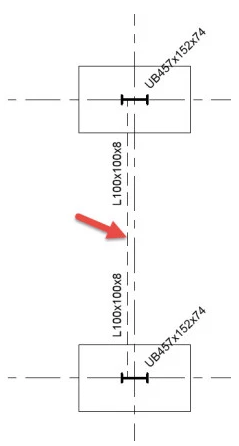
    In the image below, you can see some vertical X-bracing with the start and end attachments attached to the correct levels, with the option of adding offsets from each of these levels.


    I have used the Equal Angle to create the bracing, with both angles in the same plane, hence the clash.

    This can easily be resolved by using the y offset value on each member. The analytical line remains centred, but the physical elements will be located correctly.


    The bracing is automatically represented in a plan view and can be marked. The standard in the UK is to show a parallel line on the outside for bracing above and a parallel line on the inside for bracing below.

    You can control the type of representation and spacing in the Structural Settings dialog box.


    Finally, if you want to tidy up the bracing and make the drawings look a little better you can either use 2D detail components to represent a connection or use the connection tools to add 3D connections.

    This is just one area you will learn more about by attending one of our Excitech’s Revit Training courses.

    This article was originally posted on the Revit Structures Blog page.

    Wednesday, 8 August 2018

    AEC Workflow for Visualisation and VR


    by Geoff Alder

    I have been delivering training on Autodesk software for thirty years and during that time I have seen many developments and changes to the way industries adopt the software.

    AutoCAD was and still is excellent at modifying the geometry. Therefore, AutoCAD became a tool very proficient at editing in the developing progression of a project. I use the word “tool” here because the technical drawing was an evolving document and a tool to edit changes was needed. “I need to change what I have to what I want”. As a carpenter, I would use a plane to smooth sawn timber to have a smooth surface. It is a specific tool to do a job. I selected a plane to smooth the rough sawn timber.

    The AEC Collection has many “tools”. AutoCAD has evolved unrecognisable in the last thirty years. We also have 3ds Max, we have Revit and Revit Live. We also have 3ds Max Interactive. These are excellent Autodesk software solutions and perform very specific and capable tasks. Many clients I visit and indeed train are looking for greater understanding of the full AEC Collection. They say that they have AutoCAD operatives, Revit operatives and 3ds Max visualisers however, the focus should be on being a professional designer not a software operative. We need the Autodesk software to edit the design so we need to select the correct tool to edit and achieve our design.

    In interior design the toolset can be quite comprehensive. Much of the design will utilise a great deal of the AEC Collection and other software with regards to image manipulation.

    I believe- getting back to my early training- that using the best tool for the job leads us to focus on workflows. The AEC Collection is an excellent set of Autodesk software tools. You don’t need a comprehensive understanding of each software in the collection. You need to know the correct tool to do the job.

    My workflow training for Interior design to VR really must look at the best tool for the job. AutoCAD, Revit, Revit Live, 3ds Max and 3ds Max interactive are the primary tools in the Collection. Let’s look at the design and choose the correct tool to evolve the design. A rather famous quote says “When you only have a hammer everything is treated as a nail”.

    Saturday, 21 July 2018

    On Track with Dynamo and Revit at Autodesk University London

    by Lawrence Hooker, Excitech
    I recently attended Autodesk’s main UK learning event, Autodesk University London at Tobacco Dock in London’s East End. The two days were filled with industry presentations, hands-on-labs and plenty of opportunities to network and connect with like-minded individuals.

    The general theme for most of the event was the increasing use of automation and convergence of the design, manufacture and construction industries. One of the highlights was listening to Jaimie Johnston of Bryden Wood discussing how they have used software technologies such as 
    AutodeskDynamo to automate the design and installation of highly complex panels for the Crossrail project.

    I was lucky enough to be able to present a class on the automation of trackside structures using 
    Autodesk Revit, Civil 3D and Dynamo with a little Infraworks and Recap for as-built structures.

    During the presentation, we explored the automated design of rail platform structures and looked at parameters and data to assist with the setting out of the precast components for the construction phase. The workflow below shows how you can capture an existing platform and then use the Autodesk 
    AEC Collection to process and index the scan data, extract features using Autodesk Infraworks and then utilise Autodesk Dynamo, Civil 3D and Revit to produce detailed design and construction drawings.

    Most of the structures are related to the centreline of the rail track and, as such, can be offset and automated with Dynamo. For example, the platform has a precise offset and level from the rail that follows the cant and vertical profile. This very fact makes it extremely efficient to place the elements with Dynamo, especially when the track is on a curved alignment.

    Explore Autodesk's AEC Collection here

    A recording of this AU London presentation is available here.

    Monday, 25 June 2018

    Understanding the Autodesk “Switch”

    Since the introduction of term-based subscription licensing from Autodesk, the options for customers and the way they purchase licences has changed considerably. New perpetual licences were discontinued for new sales in 2016, with those on maintenance plans offered the option to switch to subscription in 2017. There are several implications to switching, but first, it is important to understand what it means.

    Let’s start by separating the various “switch” scenarios.

    1. Subscription to a Collection: an existing individual product subscription is converted to an Industry Collection
    2. Maintenance to Subscription: a maintenance plan is converted to a subscription for a comparable product
    3. Maintenance to a Collection: a maintenance plan for an individual Autodesk software product is converted to a subscription to an Industry Collection
    The first scenario involves moving an existing subscription to an Industry Collection and is only available to customers who are already on a subscription for an eligible product or design suite.  This does not change the current licensing model, it solely changes the product currently subscribed to.


    Scenarios 2 and 3 on the other hand involve relinquishing a perpetual licence on maintenance plan for a subscription, entirely moving to the new licensing model. At the time of switching, you can choose to move to the same Autodesk software product (option 2), or to an Industry Collection, such as the AEC Collection (option 3). These options are only available 90 days before your maintenance plan expires, with new subscription contracts active the day after expiration.


    The key difference when moving to subscription from maintenance, is that your price, for same product switches is approximately the same as your maintenance plan, significantly lower than a newly purchased subscription. Moving to a Collection affords an approximate 60% discount when compared to a new Collection subscription. 


    To explore your licensing options watch our video explanation.


    As a general rule of thumb, for customers who use two or more Autodesk software products per user, moving to a Collection is often the best route. The Architecture, Engineering & Construction Collection (AEC Collection) has seen considerable improvements since its introduction. Additional products such as Advance Steel, Fabrication CADmep, Robot Structural Analysis to name a few, are offering customers additional functionality, improved workflows and in some cases, lowering the overall licence requirement.

    There are a myriad of options and considerations for your licence management – and we recommend you talk to us. We can evaluate your requirements and advise on the best options for you moving forward.

    Wednesday, 30 May 2018

    What You Need To Know About SketchUp Layout


    SketchUp is one of the most popular 3D modelling software solutions in the world.

    Here are a few key facts:
    • 33,500,000 Annual Activations
    • Over 1,000,000,000 completed Projects using SketchUp
    • 109,000 followers on Twitter
    • 759,000 followers on Google +
    • 370,000 likes on Facebook

    An intuitive and quick to learn 3D conceptual design modelling platform, SketchUp enables more participation and collaboration across workflows.

    However what is less known is the Layout tool in SketchUp and I’ve been asked many times recently “What is Layout, what does it do”?

    LayOut is a tool for creating documentation from your SketchUp model and is part of the SketchUp Pro Suite.

    Layout combines SketchUp models with text and 2D vector illustration to help you produce beautiful presentations, permit submittals, construction documents, and other dimensioned drawings. It allows you to produce professional drawing sets, provides powerful dimensioning, drawing and page layout tools to create working drawings and presentations from SketchUp models.

    How it works

    You start in SketchUp, draw your project and create scenes to show the different views. You can send the file to LayOut, add dimensions, labels, other text, photos and then export a PDF file to send to a client or use it to do a presentation on screen.
    The dynamic link between the SketchUp model and the LayOut document means that any edits you make in your SketchUp model, will be reflected in the LayOut document. Drawings can also be exported as DWG/DXF files for use in any CAD program and you can combine dimensions, text, and graphics, add logos and title blocks to LayOut templates for brand consistency.

    LayOut also has the ability to assign different drawing scales to SketchUp model views and dimension them without leaving LayOut and without using a separate CAD tool.

    Drawings are dynamically linked to 3D models and SketchUp models are dynamically linked to your LayOut file so any changes you make in SketchUp are automatically reflected in your documents.

    Lastly, you can link to files in the cloud via Dropbox, Google Drive or Trimble Connect.
      
    A single LayOut document can be used for both printing and on-screen presentations as well as to create high-resolution large format prints which you can export as PDF files for onward distribution, or to present directly from the application... in 3D.

    Explore LayOutby watching the videos below:


    To learn more about SketchUp, please contact Excitech – https://www.excitech.co.uk/Products/SketchUp-Pro

    What’s New in AutoCAD Electrical 2025

    This blog will examine what’s new in AutoCAD Electrical 2025. Automatic Reports Enhancement In AutoCAD Electrical 2025, you can now cre...