Monday, 18 April 2022

What’s new in Autodesk Revit 2023 for Structures

Each year Autodesk releases an improved version of Autodesk Revit, with new features. Today, I will focus on new features specifically for structures.


In the Autodesk Revit 2023 release, the structural tools build on the core functionality of reinforced concrete modelling and steel fabrication modelling, but also the new analytical automation. Here are the key features and tools relating to concrete and steel modelling.

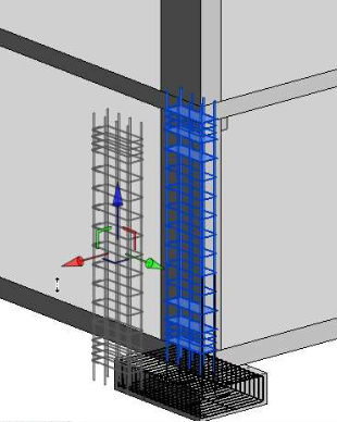
Visualisation of Rebar in 3D View

Making rebar visible in a 3D view has been simplified. With the rebar selected, in the view visibility states dialogue box, you only have the view unobscured option to tick. The rebar will automatically view as a solid when your view is in the Fine Level of Detail.


Propagate Rebar

A new feature is the Propagate Rebar; with the rebar selected in a host object, the propagate rebar tool will appear. You can select individual or multiple ‘like’ hosts to copy the rebar.


Displaced Rebar

A pasted feature that now works with rebar, select the rebar in a host object and use the standard displace elements tool to reposition the rebar in your view as desired. You can add path lines and reset the displaced bars.

Multi Leader Tags for Rebar

Use the standard tag by category tool to tag a rebar set, you can add additional bars from that set to the tag; you can also control the leader lines with multi or single leaders.


Analytical Automation

In Autodesk Revit 2023, we now have Analytical Driven Modelling; this differs from the derived analytical model as contextual, analytical elements are not created automatically when the physical model is created. We have new feature capabilities such as Analytical Member, Analytical Panel, Analytical Node, and Analytical Openings.

We also have a new Automation feature to generate a structural analytical model based on selected physical elements.


Steel Connections Automation

The Connection Automation feature can automatically apply popular typical steel connections and create your own libraries by expanding/customising the predefined libraries. The customisable automation rules for the steel connections are run by the Dynamo player. 


To learn more about Autodesk Revit, please visit our product page or call us on 0345 370 1444 or email info@symetri.co.uk


Thursday, 31 March 2022

Webinar recording | Introducing Symetri’s Modular BIM Training (including ISO 19650)

All those engaged in the delivery of a construction project, across the complete project life cycle, is now starting to appreciate the increasing importance of BIM | ISO 19650 and its value in improving supply chain collaboration and process efficiency. Therefore, keeping up to date with the latest workflows, processes and standards is essential.

We understand that one training course does not fit all due to the nature of each individual business, and the differences in where you are on your BIM journey. Therefore, Symetri can help your teams refresh and update their knowledge and understanding of BIM | ISO 19650 and Information Management through modular based learning. Our BIM expert and Principal Consultant, Daryn Fitz, has established over 26 modules to give you the flexibility and power to:

-          Configure your own content,

-          Develop your own training programmes for your employees,

-          Keep up to date with the very latest standards, methods, and processes,

-          Maximise knowledge retention and investment.

Watch this webinar recording, to see how our BIM training programme works, explore the 26 modules currently available, and book a meeting with us to customise your own BIM training course.

https://www.youtube.com/watch?v=EYFHLNRNGZA

https://www.symetri.co.uk/campaigns/bim-surgery-build-your-training-programme

Tuesday, 29 March 2022

What’s New in AutoCAD 2023?

Our Application Specialist Geoff Alder provides an overview of the new features and updates in AutoCAD 2023.

1. Traces

The traces feature found on the collaborate tab monitors and logs redline revisions.


Opening the traces pallet in the first instance shows that there are no traces in the drawing.


If we use the Markup Import feature, we can then overlay a red line markup. This can be an image file i.e., jpeg, png, pdf. I have used a pdf with a simple redline markup on this drawing.

Clicking on Markup Import brings up the dialogue.

The Markup Import has discovered the two redline markups. One in text form and one in hand sketched detail. We can then extract the details and have them on the drawing as a markup.

The markup is now listed in the traces pallet, providing users with a time that the redline edit was added to the drawing.


2. Copy Base

The copy base feature in AutoCAD 2023 is efficient in a workflow. It provides a basepoint in the first instance in the lower left extreme of the geometry.


3. Polylines

Polylines are often used to create boundary areas and closed lines. In plotting vertices to create the polyline, we have to continue in one direction because the vertices are numbered to describe the direction of the polyline.

If we add a vertex at the last vertex, this provides an additional vertex which increases the polyline length. If, however, we add a vertex at the start of the polyline, we are adding a new vertex in position two and not adding to the length of the polyline. This means we can right click on the vertex on either end and choose “Extend vertex” which will extend the polyline at that point. This can be a great time saver in creating clean and efficient polylines.

[Can we have a screenshot]


4. Display - View Tab

With the view to display options, we can now detach a View Tab in AutoCAD 2023 and have it floating; thus allowing it to be moved to a second monitor if required. The view also has its own command line making it easier to focus on a view and have the option to input commands in the same line of sight.

[Can we have a screenshot]


5. Display - FASTSHADEMODE

On display in AutoCAD 2023, we see a new command called FASTSHADEMODE. This takes advantage of newer GPU to provide a superior illuminated 3D view.

[Can we have a screenshot]


Overall, the new features & updates in AutoCAD 2023 are stable and can be used as part of everyday workflows.

Watch the video below to see these new features in action:

https://youtu.be/ldmYQ6nMnZw (embed)

To learn more about AutoCAD, please visit our product page or contact us by email  info@symetri.co.uk or telephone 0345 370 1444.

Wednesday, 23 March 2022

iLogic Parameter Types

It’s logical to consider that the order of the code in your rule can determine whether it needs to be run twice to complete or not, however there is another cause for this that many people are unaware of and that’s what I will cover today.

The different types of Parameters.

There are two different types of Parameters and they both behave differently which can affect the outcome once a rule has run. This first type is the most common parameter- the “double click the name in the rule editor” blue parameter.

This parameter does what it needs to, including updating in the rule if you rename the parameter in your model. This Parameter will hold onto a value, and only change to that value when the rule finishes executing.

This characteristic of the blue parameter can cause problems.

Let’s examine the example below.


If I know Frame_Width is 100 when my rule starts, I expect the code to make the Length of the Horizontal_SHS component 200. But that’s not the case. The reason for that is after changing the Frame_Width to 200, we now know it will hold that value until the rule finishes, then update to 200. As a result, the Frame_width that is used to drive the length of the SHS part is still 100. Running the rule a second time will cause Frame_Width to be the expected 200 and the component will update correctly.

There is a way around this characteristic, and here Parameter type becomes useful.


Enter the Purple and green parameter, technically referred to as a “Dynamic Parameter”. This parameter uses a String indicated by the “Quotation marks” and won’t update on its own if you change the name of the parameter. On the surface they play the same role, however the dynamic Parameter alters the outcome.

If I was to run the same code but using a dynamic parameter instead of the normal blue parameter, we would get the desired result the first time.

The reason for that is a dynamic Parameter forces the parameter to take the new value as soon as its set instead of waiting for the end of the rule. After the first line, Frame_Width will be 200, and as a result the Length of the SHS part will be 200.

If you find your rules need to run twice, check the order of the code in the rule remembering it runs top to bottom followed by what type of parameters are getting the values needed to execute correctly. For tricky cases, combine your checks with the iLogic Logger in my previous Episode.

With each Inventor release, Autodesk adds new features and abilities in iLogic, so if you’ve used it before or considering using it, contact us. We provide various iLogic training from the very basics to more tailored courses to help you get up to speed with iLogic.


Autodesk Fusion 360 – What is the Product Design Extension?

Autodesk have released another extension for Fusion 360 on 18th Jan 2022.

The extension is the start of a new set of product design tools to help automate multiple processes that tend to take longer if executed individually. This automation of events is, the beginning of how Autodesk will add automated workflows into Fusion 360.

The new features are manufacturing process aware, meaning they are material property driven allowing multiple features to be added in one command. This is similar to how sheet metal works currently in Fusion 360. These rule-based features mean that designers now have control over how they design plastic components.

The plastic commands are only the beginning of how this new extension will shape the way we automate in the application.

Autodesk currently has the following to offer,

  • Assign and arrange materials
  • Web
  • Boss
  • Snap fit
  • Geometric Pattern

NOTE: Access to these tools/commands are only available when you purchase the Product Design Extension (PDE).

Plastics Rules

The following commands are at the heart of the new extension:


Assign Plastic Rule – This assigns the rule that a component will use to automatically control the properties of plastic features, physical material and thickness.

Manage Plastics Rule – This command manages the use of plastics rules in your design automatically.

Some tips to apply and manage:

  • Plastic rules in your design are active to the document. Plastic rules in the library are stored in the cloud.
  • Remember to assign a rule when you start your design.
  • You can set a rule as default by right-clicking and choosing “set as default”.

Web

The web command is part of the out of the box Fusion 360 solution but with the Product Design Extension users can now add more to this feature automatically adding fillets and draft angles.

With all three features being controlled by material and thickness and the addition of adding fillets and a draft angle means these features are added more quickly

Boss

From a sketch with points this new feature will create a boss with a fastener that can be manipulated in terms of head and drive properties.

The preview of this can be seen with one click.


You can see how well the preview looks and how the section moves as you move around the model.

NOTE: As you start to use these additional features you will see the dialog boxes have pre-sets, if you are familiar with Autodesk Inventor Professional you will know how beneficial this pre-set can be, this is a great new addition to the dialog boxes.


As you complete the feature you will see that all elements of this command have been updated in the 3D model but there is still so much to show here, what happens when you make a change to the material which controls the thickness?


The shell is controlled with the thickness from the material rule. The component is activated, and the rule is then changed.


These changes reflect the shell, and the thickness is updated.

Now this is a very useful addition. Like we have seen in the sheet metal environment for a while in Autodesk Inventor and Fusion 360 these types of changes are crucial in our workflow to save time.

Snap Fit

The snap fit command is used to create cantilever snap fit features in your plastic components. These features allow solid bodies to have fastening design incorporated into them in a simple click.


Parallel and perpendicular hooks can be applied by using sketched points.


Geometric Pattern

The geometric pattern tool will give you the ability to create a pattern using size and distribution gradients. It can also be used for custom shapes.


I think favourite addition in this release is the additional assembly features. Keep an eye out for the next blog and video featuring other additions in the Jan 2022 release. 


Thursday, 10 March 2022

Webinar Recording | Autodesk Inventor add-ins – What is available for me?

This webinar recording takes a look at Autodesk Inventor’s complete portfolio, made up of powerful add-ins at hand within the Autodesk Product Design and Manufacturing Collection subscription.

https://www.symetri.co.uk/insights/video-library/autodesk-inventor-add-ins-what-is-available-for-me

The add-ins include:

  • Tolerance Analysis
  • Inventor Nesting
  • Inventor CAM
  • Inventor Nastran
  • Factory Design Utilities

These add-ins are designed to help in supercharging your workflows, driving efficiency and aid  you with getting the most out of your subscription.

By watching the video, you will learn:

  • Which applications are available with your subscription?
  • An introduction to use cases for each add-in
  • Digital Prototyping to save time and money 

For more information, please get in touch with by completing the form on the Autodesk Inventor page. Alternatively, please call us on 0345 370 1444.


Saturday, 26 February 2022

Three main goals of integrated PLM

What is most important when looking for a PLM system?

PLM is about information, how it is produced and handled and shared across a whole company. It can be considered as the backbone of everyday operations and a practice that helps define and reinforce the competitive advantage.

When considering PLM and the software you use to implement it you should consider its reliability in achieving the following three main goals:

  • Design efficiency and productivity
    Are you able to deliver the correct design data to any user, on any device, across the company? By securely storing and managing engineering design data and related documents, you can quickly find and re-use design and engineering data.
  • Cost reduction
    Are you able to free up design engineers to focus on innovation rather than administration? By integrating product information with Procurement and Production you can deliver improved quality at lower costs.
  • Speed to market
    Have you automated data sharing across your supply chain? By ensuring data accuracy for each delivered area, you can support field management and turn users into advocates; favourably impacting reputation and facilitating sales growth.

Make it easy, make IT smarter

PLM addresses the day-to-day issues that may arise from inconsistent information sources and methodologies but can only do this if they’re all brought together in one platform. Such a platform can provide an automatic, and automated, connection between the constituent phases and practices involved in the overall PLM process.

Sovelia provides a lean approach to PLM

Our Sovelia digital platform for engineering and PLM enables you to provide your teams with the solutions they need for seamless collaboration, to link your processes and systems, and optimise your data. Sovelia drives cost-efficient practices by giving you the tools to create, innovate, and manage, effortlessly.

For further information about Sovelia or to discuss your PLM requirements please contact Symetri.  


Friday, 25 February 2022

What’s New in Factory Design Suite 2022

Model States has now replaced the Level of Detail functionality of Inventor in previous releases. When publishing a part/assembly that contains multiple Model states, FDU assumes them as different interpretations of the same part/assembly.  It is vital all have the same key parameters and parameter values.

When using model states, the 2D representation used in AutoCAD may not always match with the 3D representation. When publishing, the 2D representation reflects the active model state at publish time. When  being updated to reflect parameter changes, it will always be based on which model state was the active model state, chosen to generate 2D asset at publish time and does not reflect the various model states.

iLogic Form Enhancement

The iLogic Form now can be accessed straight from the asset's context menu.

Select an asset or multiple assets.

  1. Right-click to display the context menu.
  2. Hover over Factory to display its drop-down menu.
  3. Click Open iLogic Form.


Manage Revit AnyCAD references in Vault for Factory Layouts

Revit AnyCAD references included in Factory Layouts can be managed in Vault from the Factory Vault Integration, the same way as regular Inventor assemblies.

You can manage libraries, store, view, and download assets by using Vault Professional integration features.


The Vault Assets folder includes assets stored in Vault and appear in the Factory Asset Browser. The structure of the folder mirrors the library structure in Vault. If any folders are added or deleted in Vault, the change is reflected within the Asset Browser.

The Inventor AnyCAD capability allows you to:

Revit interoperability functionality must be installed in order to interact with Revit models to both extract and record building information. If you do not install the Revit interoperability sub component, you are unable to import and export the Revit files.

Inventor BOM settings in FDU asset publishing

Bill of Materials settings is now able to be selected during asset publishing FDS. Inventor Document settings can be used to set the default BOM structure. Changing it during asset publishing will also change the document settings.


Control the BOM setting from the "Convert to Assets"

Bill of Materials settings can now be adjusted during “Convert to Assets”. The selected option updates the Inventor Document settings.

Imported CAD models can also be converted into factory assets using the Convert to Assets feature.

The Convert to Assets feature allows you to convert imported CAD models into factory assets. If, for example, you receive component data from a supplier that you want to evaluate or run through collision detection, this feature can be used to quickly convert that data to a factory asset for placement in your layout designs.


Create a sub-layout of selected assets using Inventor/AutoCAD.

Multiple objects can be selected to create a sub-layout. The advantage is to make it possible to break the specific items or areas into multiple sub-layouts for individual designers to work on.

The Create Sub-Layout command creates a sub-layout within the current layout.

Select the Factory tab > Layout panel > Create Sub-Layout .


3D factory assets and/or Inventor part, assembly, existing sub-layout when selected will be included in the newly created sub-layout.


Similarly in AutoCAD, Select the Factory tab > Layout panel > Create Sub-Layout 

Select multiple objects to create a sub-layout, making it possible to break the specific items into various sub-layouts for individual designers to work on.

The new Factory Design update 2022.1.1 is now available from your Subscription account.

Visit our website for further information about Factory Design Suite or feel free to contact us at Symetri to arrange a consultation with one of our technical specialists.


Friday, 18 February 2022

FEA Made Easy.

As a designer and Engineer you can spend a significant amount of your time trying to get original CAD data ready for FEA studies. This entails suppressing non-structural parts, supressing features like holes and bolted connections and in extreme cases remodelling.

This is particularly true for welded and bolted fabrications including sheet metal and structural frame type components. This is required to make the mesh process as smooth as possible whilst trying to keep element numbers sufficiently low to enable faster FEA run times.

Taking out geometry simplification and meshing can make the FEA process simple and easy to use allowing designers and engineers to adopt FEA in their workplace to make optimised and innovative products.

Altair SimSolid simulation technology for designers, engineers, and analysts eliminates geometry preparation and meshing: the two most time-consuming, expertise-extensive, and error-prone tasks performed in a conventional structural simulation.


Read how our customer Pentre Engineering has introduced SimSolid to their design process and is achieving super-fast structural analysis in their designs and what took them 3-4 days of effort is now reduced to a matter of hours.

Find out more about SimSolid for yourself and download a free trial.

How to Setup and Update Title Blocks Within Electrical Projects

This blog looks at the setting up and update of the title block information within existing electrical projects using AutoCAD Electrical.  


Title Block Setup

If you already have a company template setup within AutoCAD with an attributed title block this can be used to integrate the title block setup process from AutoCAD Electrical.

The title block setup procedure begins via the Project Tab > Title Block Setup. 

The following title block setup methods are available within AutoCAD Electrical in the sequence order highlighted below:

·  WD_TB (Attribute) – Invisible attribute that is stored within the block definition of the title block.

·  <Project Name>.wdt – Project specific template mapping file stored within the active project folder.

·  default.wdt - Default template mapping file stored within the active project folder.

· default.wdt - Default template mapping file stored within a specified location within the application options (Files tab) under the ‘Support File Search Path’.

The attributes within the title block need to be mapped to either project values (Project Descriptions) or drawing values (Drawing Properties) as shown in the example below:

Project Values


Drawing Values


The attributes can be mapped to the values via ‘Pick’ or from the drop-down menu option, once mapped, the title block setup process has been completed.

Title Block Update

The following procedure must be carried out in order to update the title block with the latest project and drawing values:

1.  Run the Title Block Update within the ‘Project Tab’

2.  
Select the relevant project and drawing values to be updated (Example below).


The values can be updated within the active drawing, specific drawings, project sub-folders or across the complete project.

For further information on the benefits of using AutoCAD Electrical for your electrical design, feel free to contact us at Symetri to arrange a consultation with one of our electrical specialists.

We offer scheduled AutoCAD Electrical essentials training, as well as be-spoke training tailored to your requirements to help you work smarter for a better future. 


What’s New in AutoCAD Electrical 2025

This blog will examine what’s new in AutoCAD Electrical 2025. Automatic Reports Enhancement In AutoCAD Electrical 2025, you can now cre...