Friday 24 April 2020

How to introduce Generative Design into your Workflows?


Welcome to the second part in this series of articles around Generative Design within the Manufacturing sector. The next local step, after setting the scene in the previous article https://excitech.co.uk/Insights/Blog/April-2020/Generative-Design-for-Manufacturing-Article-1, is to dive deeper into how you can look to introduce Generative Design into your current workflows.

The only product which currently includes Generative Design is Autodesk Fusion 360. However, do not let that put you off if you are an existing Inventor user. Most people these days will be utilising Inventor as part of the Product Design and Manufacturing Collection, which also includes access to Fusion 360. However, I would recommend you speak to your license Contract Manager to confirm this. But assuming you do have access to Fusion 360 as part of your package, you can simply download/install, then start to explore.

The first thing you will need to do, when approaching Generative Design. Is to consider your requirements, this can include things like:
  • Are there parts of the design which need to be kept, i.e. holes or clearance areas?
  • Are there manufacturing constraints? What manufacturing processes do you have access to?
  • Are there areas of the design where no material should appear or obscure?
  • Where are the constraints on the design, i.e. fixings or bolts?
  • Consider your objectives, is it light weighting or increased stiffness?
  • What loads is the design subject to, including misuse?
  • What materials are available?
Following this, you will need to generate some geometry in Fusion 360, to represent the above scenarios. So, if we take a simple example of a clevis bracket, as per the below, which needs to consider the fact that it will be bolted to a wall with a pulling force of 50N. Manufacturing considerations are access to 3 and 5 axis CNC, alongside Steel and Aluminium material stocks.


The geometry we need to create for this scenario, is perhaps not what you would expect. As you are effectively modelling the constraints of the problem, not the outcome geometry, which is more traditional. Therefore, for this example the modelled problem is going to be something like the image below.


Where the Green items are Preserve regions and the Red items are Obstacle regions. Put more simply, the Green areas are parts of the end design we must have, i.e. holes for the bolts to the wall and where the clevis will attach. The Red areas are regions where we do not want any material, i.e. clearance for bolt heads and tools, or where we need the outcome to have a flat bottom to attach to a wall.

Following on from this, it is a case of applying loads and conditions that the model will experience during its use. It is worth considering additional operating considerations at this point, to consider product misuse. For example, would you want the clevis bracket in this example to stand up to a side impact? Below you will see the loads and constraints required for our bracket in this sample.


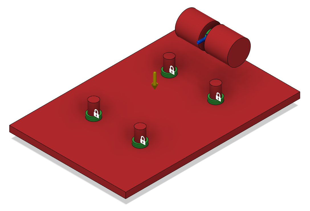
Where Blue arrows are loads with direction of force, Green arrows represent Gravity and its direction on the part. The Padlock items are Fixed constraints applied to the component, in this example illustrating the points where the bracket would be bolted to a wall.

Now you need to make choices around how you want to manufacture the part, what materials you want to use and your study objectives.


At this point and prior to running a study and using up Autodesk Cloud Credits in the process, it is well worth doing a Preview. This will indicate where material will go and just as importantly where material should not go.


Once all the above has been done and assuming the Preview is looking sensible, with no material starting to form where you do not want it etc., then you are ready to run a study. At this point, you will be advised of your Autodesk Cloud Credit usage, at the time of writing this is 25 Credits per study run (with multiple outcomes). All the information will be uploaded to the cloud and processed accordingly. The Study option allows you to see the progress of outcomes during the process and investigate the differing results to compare results.

The below are some different examples from a single study, to highlight the differing manufacturing outcomes.


All study outcomes can be analysed and compared, to review how well they perform, alongside results based on the original objectives. These can be shown in different ways and the display of information can be focused on what are the important criteria for you and the study being conducted.


There could be different uses for this information, it can give you an indication of where to add/remove material from an existing design you have. It could be there to advise on a completely new design. Or you may want to directly use the generated 3D data. This data can be downloaded, upon completion of processing in the cloud in one of two formats: T-Spline or Mesh. You will be advised of your Autodesk Cloud Credit usage to do this; at the time of writing this is 100 Credits per download of a Generative Design outcome.


Once downloaded, this data can be used directly inside Fusion 360. Or the data can be exported from Fusion 360 or Teams. Or if you currently utilise Autodesk Inventor, then you have access to AnyCAD import, via the Autodesk Desktop Connector functionality.


Hopefully, this article provided a greater understanding of the workflow required with Generative Design in Autodesk Fusion 360; along with an introduction as to how you might include this alongside your current workflows in Autodesk Inventor.


If this is something you are interested in exploring further, then please get in touch by emailing us at info@symetri.co.uk


Saturday 4 April 2020

What's New in Inventor Professional 2021

Autodesk’s experienced product, Inventor Professional 2021, has now gone live. This new edition has been improved in the four key areas below:
  • Performance
  • Modernisation
  • AnyCAD
  • Automation

Performance:

As with every release, Autodesk Inventor Professional has enhanced product performance to allow for greater speeds and capability. Below you will find a list of some of the key areas they have improved:


Modernisation:

Tools have been gradually updated in line with the modernisation of the product. This year is no different, with Autodesk updating tools such as Coil, Thicken/Offset, Frame Generator and Delete Face. They have also released the new dark theme to counter issues that come with the blue light and light theme exposure. 

AnyCAD:

The interoperability between Revit and Inventor Professional has been constantly reviewed. With this release, Autodesk have incorporated the ability for Inventor Professional to read Revit 3D data. What is great about this is that it is a live connection and allows Manufacturing and Architectural companies to work seamlessly using BIM.

Automation:

The ability to automate procedures is a constant feature with each update. This year pre-sets have been added to Frame Generator and drawing templates have been enhanced to improve this aspect. 

General Part Enhancements 

Some features in the part environment have been improved with the likes of now having the ability to window select multiple bodies. Previous versions would have made you choose this by selecting on them individually in the window. This will save users a vast amount of time considering it's a small tweak, especially when working in the woodwork environment. 

Another feature they have tweaked in the part environment is the unwrap tool, which now align to specific work planes. They have also enabled coplanar holes to stay rigid; this allows for holes to keep a set distance when creating the flat pattern. 

The flange tool in the sheet metal environment has been updated to now allow you to choose a reference face. This is good as it will reduce manual calculations when trying to match an exact angle.

Frame Generator Enhancements

All the tools in Frame Generator have been updated with the modernised theme to now allow it to be docked into the properties panel. This goes hand-in-hand with some much needed adjustments that allows for a smoother workflow. Firstly, the new zoom options which allows users to see the placement of a member perpendicular to the view. Secondly, you can also zoom so the member is fit to the view of the screen. Both options provide a great new alternative when aligning your member.

Further improvements to the notch tool include a follow on from the custom ‘I’ template in the 2020 version, with Custom ‘C’ and ‘T’ Templates. Improvements like this allow for the Frame Generator environment to become a more well-rounded tool. 

General Drawing Enhancements

Sheet Set Formats in previous versions only allowed for standardisation of Borders, Title Blocks and Sheet Properties. In 2021, Autodesk have adapted this to encourage users to have sheet format templates for a few different areas including: View placement (as well as shaded properties), 
Sheet Metal Settings, Parts List and Format settings, General/Generic Tables, and Notes and Text. This is a little time consuming during the initial set up phase, but worth it in the long run. Once these are created it will not only reduce time but provide a great addition to the software by improving consistency of drawings throughout the business. 

Excitech Toolkit for Inventor

The Excitech toolkit for Inventor has also had a revamp, making it fully compatible with Inventor Professional 2021. The toolkit has been modernised to align with Inventor Professional’s theme and bug fixes from the previous release have been included. If you have any tool ideas for the toolkit or any issues installing or licensing, please feel free to get in touch at info@symetri.co.uk 

To learn more about Inventor Professional, please visit our product page here. Alternatively you can call us on 01992 807 444 or email info@symetri.co.uk


What’s New in AutoCAD Electrical 2025

This blog will examine what’s new in AutoCAD Electrical 2025. Automatic Reports Enhancement In AutoCAD Electrical 2025, you can now cre...